Installation
20169223D 5-59
To open the Control unit, remove the four flat-head screws on the
backside, and gently pull the two halves apart. Be aware that the
internal PCB's are interconnected by plugs, thus care must be shown
when putting the two halves together again.
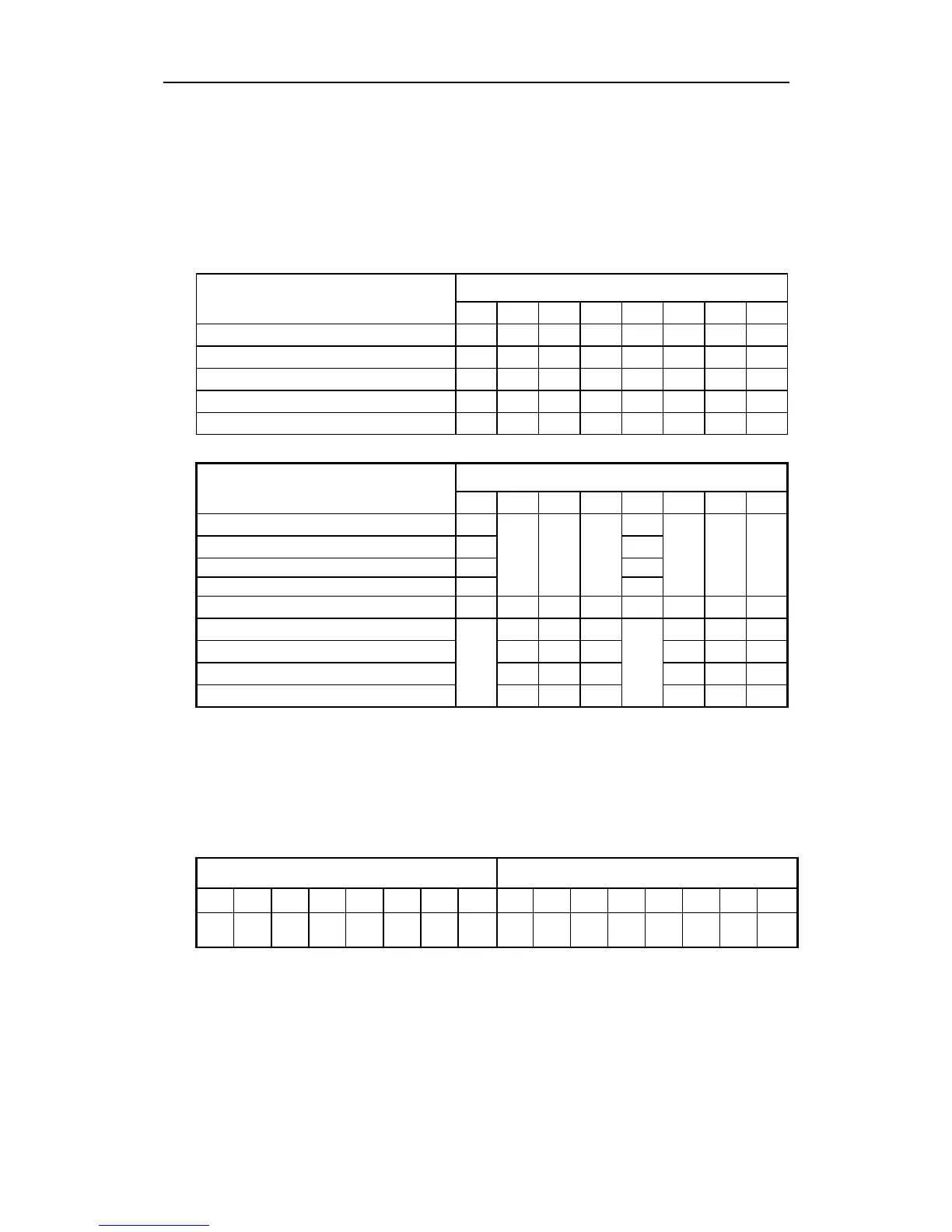
Make sure that the internal dip switches, SW1-2 are correctly set
according to the list below. The settings of SW2 only applies for
synchro input.
Gyro type selection SW1
87654321
Serial gyro 00100001
Stepper (6 steps/degree) 24, 35, 70V 00000011
Synchro 1:1, gyro ref. voltage 00010001
Synchro 90:1, -------
”
-------
00001001
Synchro 360:1 -------
”
-------
00000101
Ref. voltage selection SW2
84
150V ref. from gyrocompass 0 0
100V -------
”
-------
01
50 - 60V -------
”
------- 1 0
26V -------
”
------- 1 1
Phase voltage selection 765 321
110 - 115V 0 0 0 0 0 0
50 - 90V 0 0 0 1 1 1
20 - 24V 1 1 1 0 0 0
11.8V 111 111
Caution ! The switches SW1-7/8 must under no circumstance be set to
ON (1) when Reference Voltage is taken from the gyro
compass.
AUTOPILOT EXCITATION OF 1:1 SYNCHRO
SW1 SW2
8
1
7
1
6
0
5
1
4
0
3
0
2
0
1
1
8
1
7
1
6
1
5
1
4
1
3
1
2
1
1
1