Section04ENGINE
Subsection 05 (PTO HOUSING)
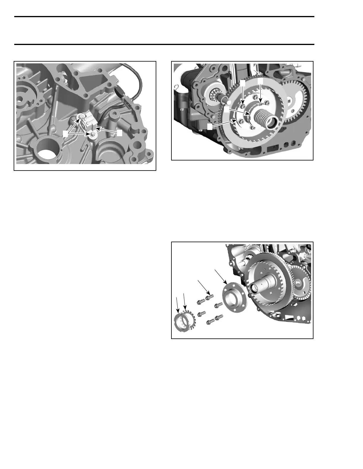
R1503motr341A
1
2
1. CPS screws
2. CPS
Inspection
Check CPS condition. If damaged replace the
faulty part.
For electrical inspection, refer to ENGINE MAN-
AGEMENT for the CPS.
Installation
For installation, reverse the removal procedure.
However, pay attention to the following.
NOTE: Apply Loctite 243 on threads. Torque CPS
screwsto10N•m(89lbf•in).
ADAPTER SLEEVE AND FLANGE
COUPLING
Removal
Lock crankshaft with locking tool (P/N 529 035
821). Refer to CRANKSHAFT LOCKING in EN-
GINE BLOCK subsection.
Remove:
– PTO housing
– nut no. 15 using 4-tooth sprocket (P/N 529 035
960)
– retaining ring with lug no. 16
– hexagonal screws no. 17
– flange coupling no. 18.
R1503motr342A
2
3
1
4
1. Nut
2. Retaining ring with lug
3. Hexagonal screws
4. Flange coupling
NOTE: Carefully remove the flange coupling
no. 18 using torque flange remover (P/N 529 035
958).
Inspection
Check nut, retaining ring with lug and flange cou-
pling condition. If damaged, replace faulty part.
4
R1530motr343A
1
2
3
1. Nut
2. Retaining ring with lug
3. Hexagonal screws
4. Flange coupling
Installation
For installation, reverse the removal procedure.
However, pay attention to the following.
Use Loctite 243 on the cone at the flange coupling,
push flange coupling on adapter sleeve and align
the hole pattern. Apply Loctite 243 on threads.
Tighten the hexagonal screws and nut by hand to
help centering. First torque hexagonal screws to
24 N•m(18lbf•ft).
92 Te m plat e

 Loading...