Section04ENGINE
Subsection 08 (CYLINDER HEAD AND VALVES)
Loosely install screws.
Install chain tensioner.
NOTE: There can be 2 different positions to install
the timing gear on the camshaft. Basically both
positions are working well, since the camshaft and
crankshaft are locked in their proper position. Due
to some tolerances, there could be one position
which fits better than the other one. To check this,
perform the following test.
Check if screws are still loose. If screws are
squeezed by the timing gear, remove the chain
tensioner again and rotate timing gear by one
tooth clockwise. Then install the chain tensioner
again.
Tighten screws and torque to 10 N•m(88lbf•in).
Remove locking tools.
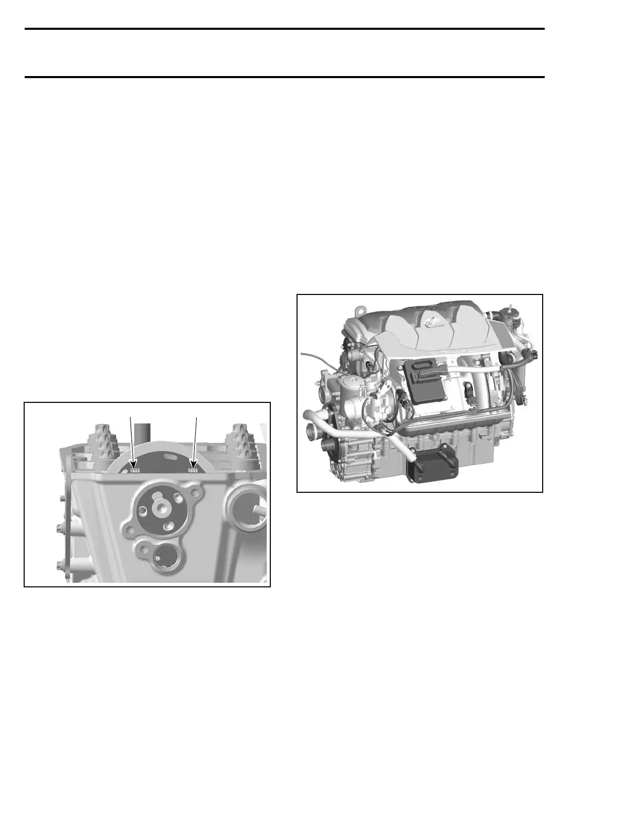
CAUTION: Crankshaft and camshaft must be
locked on TDC position to place camshaft tim-
ing gear and timing chain in the proper posi-
tion. To double check, take a look at the timing
gear lines. They must be parallel to the cylin-
der head surface.
1
R1503motr95A
1
1. Position lines
CAUTION: Ensure to remove locking tools
when finished.
TIMING CHAIN
Refer to ENGINE BLOCK section.
CYLINDER HEAD
Removal
Lock crankshaft with crankshaft locking tool
(P/N 529 035 821), refer to CRANKSHAFT LOCK-
ING in ENGINE BLOCK section.
Drain coolant (refer to COOLING SYSTEM).
Disconnect coolant temperature and camshaft po-
sition sensors (CTS and CAPS).
Remove:
– exhaust manifold (refer to EXHAUST MANI-
FOLD REMOVAL elsewhere in this section)
– engine hoses
R1503motr294A
TOPS VENTILATION HOSE
– chain tensioner (refer to CHAIN TENSIONER
REMOVAL in ENGINE BLOCK section)
– valve cover shield
– (see VALVE COVER REMOVAL above)
– camshaft timing gear
– cylinder head screws M6 no. 16
132 Te m plat e
 Loading...