Section 06 TRANSMISSION
Subsection 03 (DRIVEN PULLEY)
12, Screws
These screws are machined at there end. With
the adjustment ring set to position 0 (zero), screw
ends are flush with inner side of fixed pulley half
once tightened.
CAUTION: If any of these screws is not flush
with inner side of sliding pulley, bushings will
worn unequally.
Assemble driven pulley components by reversing
the disassembly procedure.
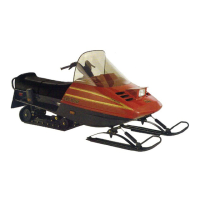
11, Cam
Coat cam interior with anti-seize lubricant.
Make sure to install proper cam. Refer to TECH-
NICAL DATA.
Cam angle is identified on cam.
A30D0XA
NOTE: For high altitude regions, a service bulletin
will give information about calibration according to
altitude.
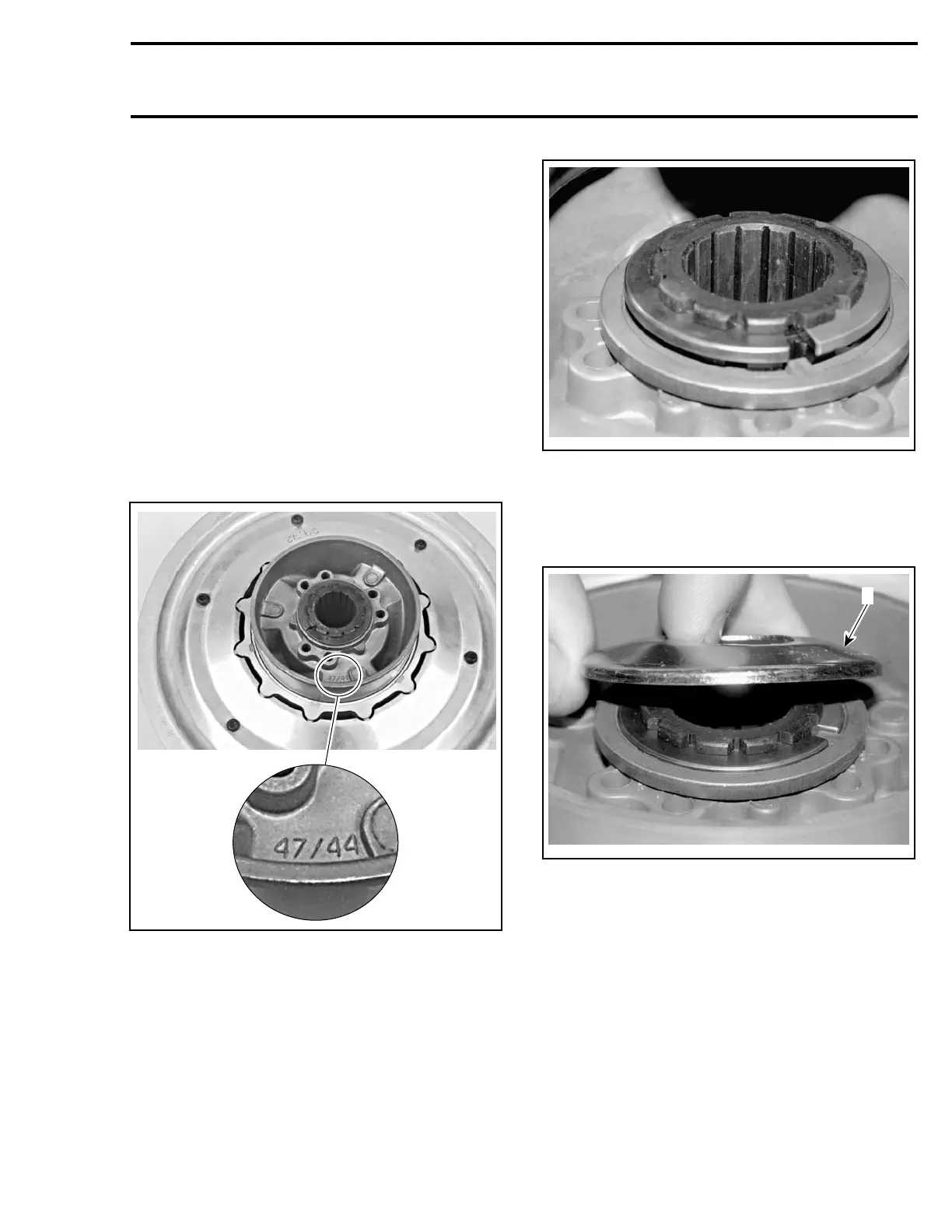
Install spacer no. 7 and half keys no. 6 as per fol-
lowing photo.
A34D0CA
HALF KEYS INSTALLATION
CAUTION: Make sure to install the proper pro-
tector no. 5. The proper protector no. 5 com-
pletely covers the half keys no. 6 and the spacer
no. 7 without touching them.
A34D0DA
1
1. Proper protector
INSTALLATION
5, Countershaft
CAUTION: Always apply anti-seize lubricant
(P/N 293 800 070) on the countershaft before
final pulley installation.
Should installation procedure be required, refer to
BRAKE then look for BRAKE DISC and COUNTER-
SHAFT BEARING ADJUSTMENT.
Reinstall the pulley on the countershaft by revers-
ing the removal procedure.
Te m pla te 229

 Loading...