Section04ENGINE
Subsection 09 (ENGINE BLOCK)
PISTON RINGS
Removal
Remove piston ass'y as described above.
Remove rings.
Inspection
Ring/Piston Groove Clearance
Using a feeler gauge measure each ring/piston
groove clearance. If the clearance is too large, the
piston and the piston rings should be replaced.
RING/PISTON GROOVE CLEARANCE
mm (in)
NEW MINIMUM
RECTANGULAR
0.025 mm (.001 in)
TAPER-FACE
0.015 mm (.0006 in)
OIL SCRAPER RING 0.020 mm (.0008 in)
NEW MAXIMUM
RECTANGULAR
0.070 mm (.0028 in)
TAPER-FACE 0.060 mm (.0024 in)
OIL SCRAPER RING
0.055 mm (.0021 in)
SERVICE LIMIT
ALL
0.15 mm (.006 in)
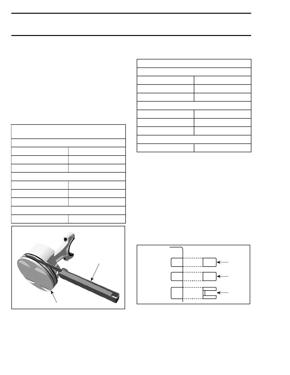
2
R1503motr32A
1
1. Piston
2. Filler gauge
Ring End Gap
RING END GAP mm (in)
NEW MINIMUM
RECTANGULAR 0.15 mm (.006 in)
TAPER-FACE
0.15 mm (.006 in)
OIL SCRAPER RING 0.15 mm (.006 in)
NEW MAXIMUM
RECTANGULAR
0.35 mm (.014 in)
TAPER-FACE 0.35 mm (.014 in)
OIL SCRAPER RING
0.30 mm (.012 in)
SERVICE LIMIT
ALL 1mm(.04in)
Measure position for ring end gap in the area of 8
to16mm(.315to.630in)fromtopofcylinder.
NOTE: In order to correctly position the ring in the
cylinder, use piston as a pusher.
Using a feeler gauge, check ring end gap. Replace
ring if gap exceeds above described specified tol-
erance.
Installation
For installation, reverse the removal procedure.
Pay attention to the following details.
Install the oil scraper ring first, then the taper-face
ring with the word “TO” facing up, then the rect-
angular ring with the word “T” facing up.
A31C2NA
1
2
3
1. Rectangular ring
2. Taper-face ring
3. Oil scraper ring
CAUTION: Ensure that top and second rings are
not interchanged
164 Te m plat e
 Loading...