Section 06 TRANSMISSION
Subsection 05 (BRAKE)
CALIPER
There is one caliper installed on each side of the
vehicle. Procedure for LH and RH side caliper is
the same. Procedure for LH side is provided be-
low.
Removal
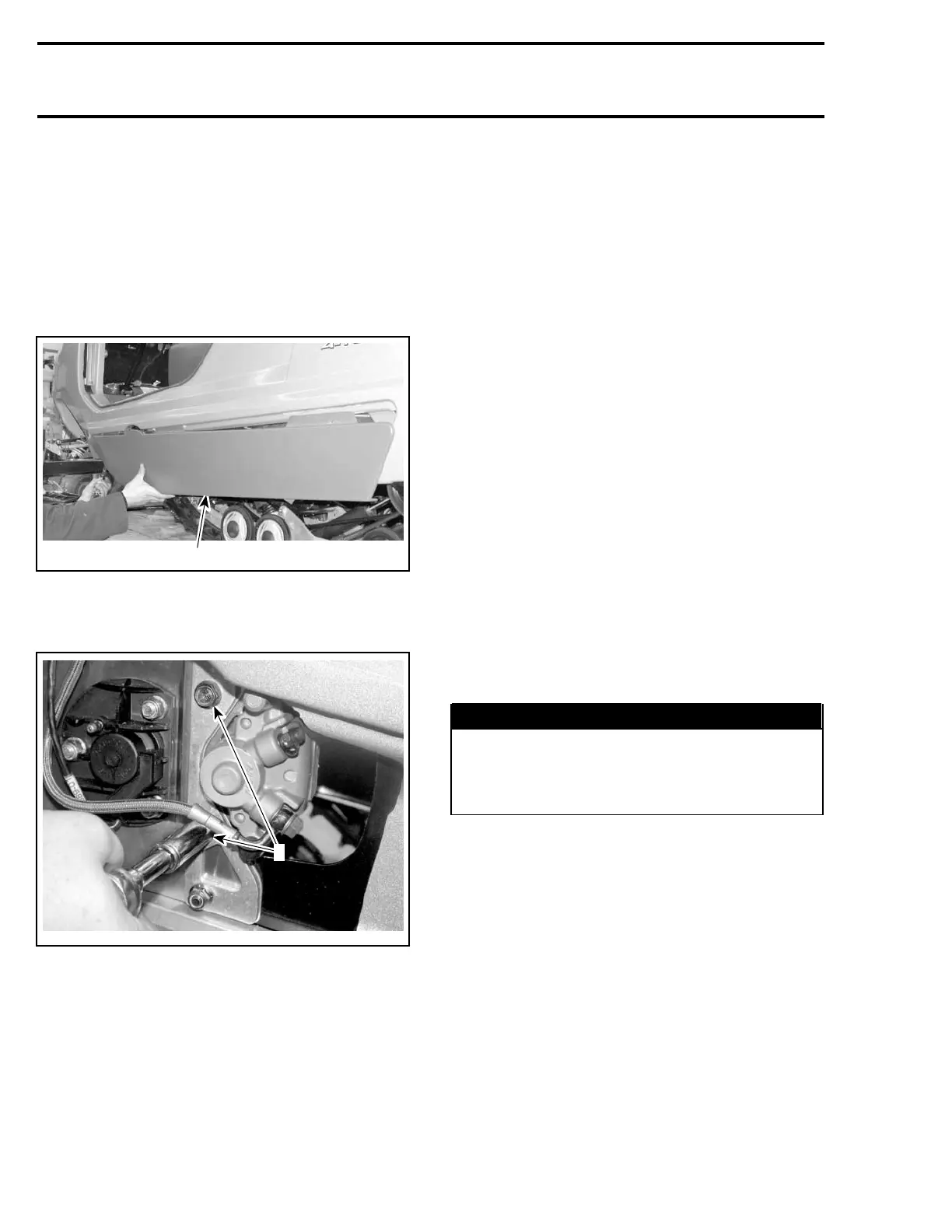
Remove the plastic molding.
1
A34D0XA
1. Plastic molding
Remove screws no. 20 and detach caliper no. 6
from the chassis.
A34D0YA
1
1. Screws
NOTE: Therearetwospacersgluedtobrakesup-
port bracket no. 10. While doing the caliper re-
moval procedure make sure to save those for in-
stallation.
CAUTION: Do not let the caliper hang by the
hose and do not stretch or twist the hose.
Unscrew the bleeder screw no. 19 and drain the
brake system completely.
To completely drain the brake fluid, continuously
press the brake lever until all liquid escaped out.
CAUTION: Spilling brake fluid on plastic, rub-
ber or painted parts can cause severe damage.
Protect these parts with a rag when servicing
brake system.
Place a container under caliper. Do not remove
the Banjo bolt no. 7 during draining.
When the system is empty, remove the Banjo
bolt. Discard the sealing washers no. 8.
Inspection
Remove brake pads no. 9, refer further in this sec-
tion.
Check pistons for scratches , rust or other dam-
ages. If so, replace the caliper as an assembly.
NOTE: Only brake pads are available as spare
parts.
Installation
Push pistons all the way in to allow caliper instal-
lation over brake disc.
Install the Banjo bolt no. 7 with two new sealing
rings no. 8.
Fill the brake system and bleed it. Refer to
BLEEDING in this section.
WARNING
Make sure spacers are between caliper sup-
port no. 11 and brake support bracket no. 10.
Use loctite 271 to stick spacers on brake sup-
port bracket.
The brake disc no. 13 must be centered in caliper.
Apply brake then check for proper brake disc po-
sitioning.
Push on appropriate caliper piston in order to
move pad inward allowing proper brake disc po-
sitioning.
Apply brake then recheck.
BRAKE PADS
Removal
Brake pads removal procedure is as follows:
– Detach the caliper from the chassis as per the
procedure mentioned above.
– Unscrew pad pins no. 12.
236 Te m plat e
 Loading...