Section 06 TRANSMISSION
Subsection 06 (GEARBOX AND FINAL DRIVE BELT)
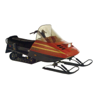
To adjust, loosen lock nut no. 8 and turn fork axle
accordingly.
A34D0MA
1
DRIVEN PULLEY REMOVED
1. Fork axle end
Before tightening lock nut no. 8, position ball joint
no. 10 90° to pivot no. 7 to allow proper ball joint
free rotation.
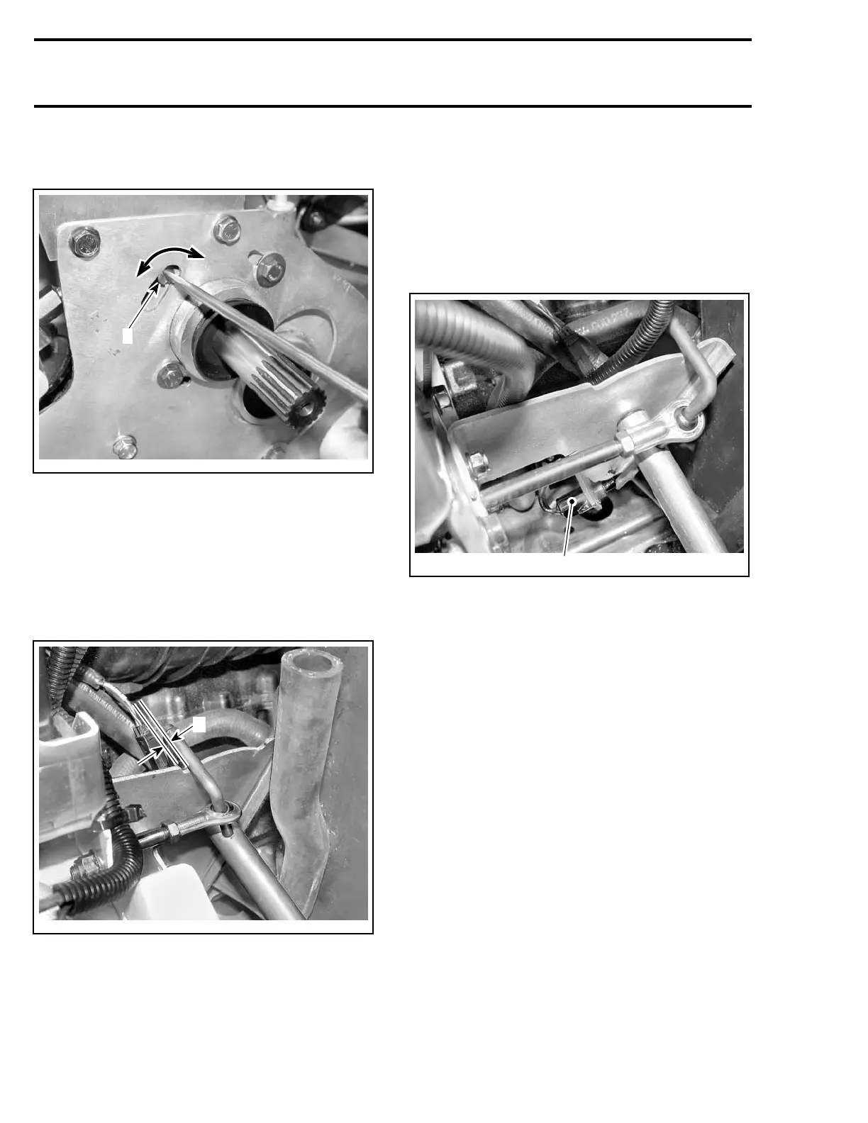
Shift in forward position.
Check if pivot no. 7 is at least 0.5 mm (.020 in)
from stopper.
A34D0NA
A
FORWARD POSITION
A. 0.5 mm (.020 in)
To adjust, proceed as described above.
Check reverse switch adjustment as described
above.
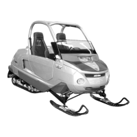
REVERSE SWITCH ADJUSTMENT
Short to ground the ORANGE/WHITE wire of
VCM. Refer to TESTING PROCEDURE.
Shift in reverse.
Reverse alarm must sound. If not, unplug reverse
switch to avoid twisting wires, loosen lock nut and
screw switch in.
A34D0LB
1
1. Reverse switch
Reconnect and check for sound. Repeat adjust-
ment as required.
Reconnect switch and tighten lock nut. Recon-
nect ORANGE/WHITE wire.
REMOVAL
Remove the drive belt and the driven pulley.
Remove the battery. Refer to BATTERY.
Remove the battery rack no. 12.
Drain gearbox oil as explained in OIL CHANGE.
Remove final drive belt from top drive sprocket as
explainedinFINALDRIVEBELT.Removethedrive
sprocket from output shaft of gearbox.
Unfasten fork axle from ball joint no. 10.
Remove transmission support no. 11.
Unbolt gearbox from chassis and remove it.
DISASSEMBLY
Unbolt the gearbox cover no. 1.
244 Te m plat e
 Loading...