Section04ENGINE
Subsection 08 (CYLINDER HEAD AND VALVES)
1
R1503motr92A
2
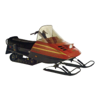
1. Rocker arm shaft screw
2. Torque angle gauge
CAMSHAFT TIMING GEAR
NOTE: Although it is not necessary to position
crankshaft to TDC for disassembly, it is a good
practice to do it, as a troubleshooting step, to
know before disassembly if valve timing was ap-
propriate.
Removal
Lock crankshaft with crankshaft locking tool (P/N
529 035 821), refer to CRANKSHAFT LOCKING in
ENGINE BLOCK section.
Remove:
– valve cover
– chain tensioner (refer to CHAIN TENSIONER
REMOVALinENGINEBLOCKsection)
– chain guide no. 12
– Allen screws no. 13
– camshaft timing gear no. 14.
NOTE: Secure timing chain no. 15 with a retaining
wire.
Inspection
Check camshaft timing gear for wear or deteriora-
tion.
If gear is worn or damaged, replace it as a set
(camshaft timing gear and timing chain).
Forcrankshafttiminggear,refertoENGINE
BLOCK section.
Installation
For installation, reverse the removal procedure.
Pay attention to the following details.
Using the camshaft locking tool (P/N 529 035 839),
lock camshaft on TDC position.
1
R1503motr94A
2
1. Camshaft locking tool
2. Camshaft on TDC position
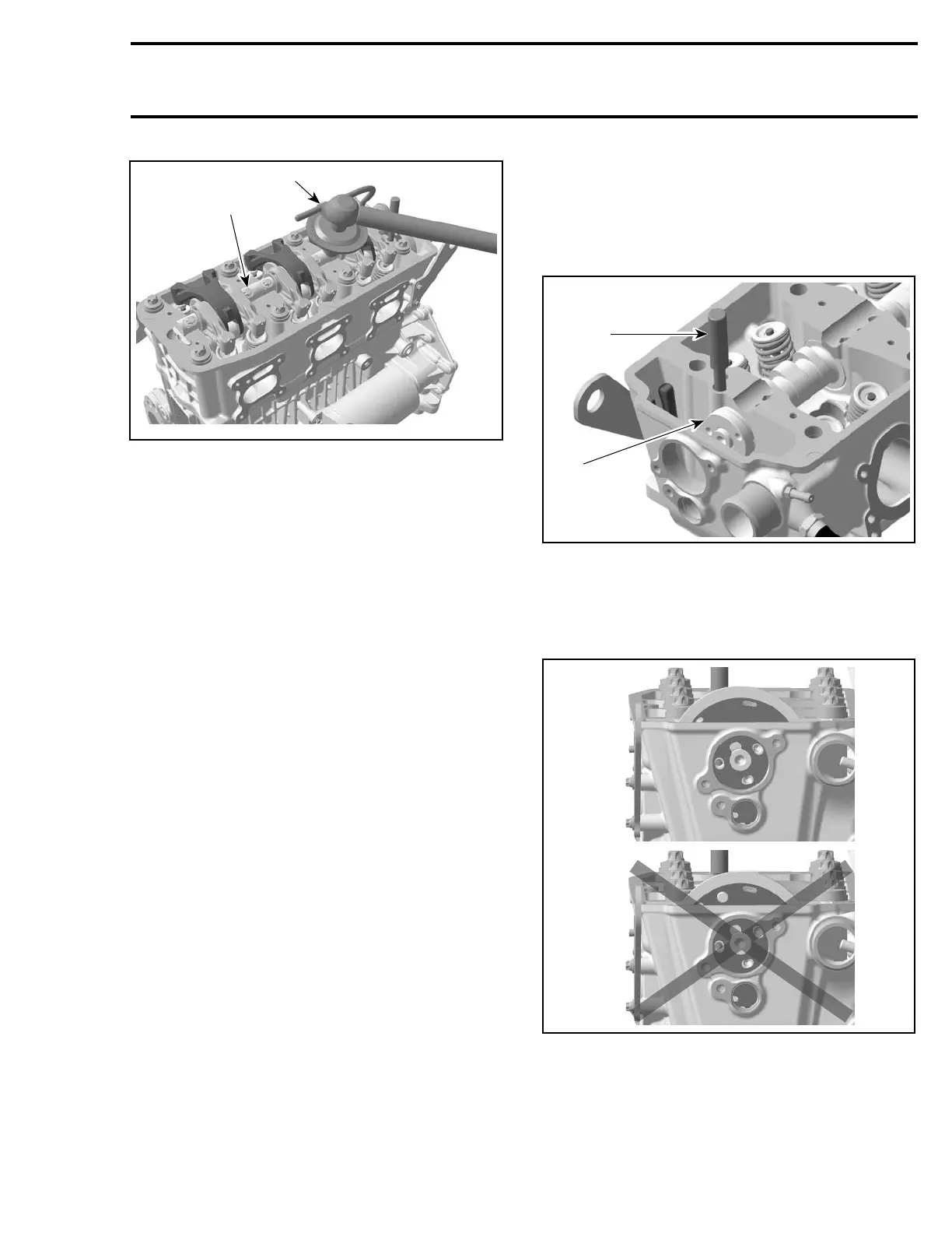
Install the camshaft timing gear with the writing
visible, i.e. to be able to see the position lines
when looking from outside of engine.
1
R1503motr97A
2
1. Good (with 1503 aligned)
2. Never
Install timing chain. Refer to ENGINE BLOCK sec-
tion.
Ensure chain guides are in place.
Te m pla te 131

 Loading...