Section07ELECTRICALSYSTEM
Subsection 01 (ALTERNATOR)
REMOVAL
Disconnect BLACK negative cable from battery.
WARNING
Battery BLACK negative cable must always be
disconnected first and connected last.
Remove air silencer, foam and belt guard.
Disconnect RED cable from alternator. Discon-
nect electric connector from alternator.
Loosen alternator belt tension. To do so, loosen
alternator mounting bolt no. 5 and retaining bolt
no. 6, then lock nuts no. 3. Turn adjustment rod
no. 2 accordingly.
Remove alternator belt from alternator pulley.
Unfasten adjustment rod no. 2 from alternator,
then remove mounting bolt no. 5. Remove alter-
nator.
NOTE: If the engine pulley or the alternator belt
needs to be replaced, refer to PTO HOUSING.
INSPECTION
NOTE: The alternator does not require any main-
tenance and must not be opened for repair work.
Inspect the housing and ball bearings for damage
or wear. In case of damage, the alternator must
be replaced. The alternator can only be replaced
as a complete assembly.
INSTALLATION
The installation is the reverse of removal proce-
dure. Pay attention to the following details.
Make sure to install a washer no. 7 on each side
of alternator mounting emboss and alternator sup-
port no. 4.
Proceed with alternator belt tension adjustment.
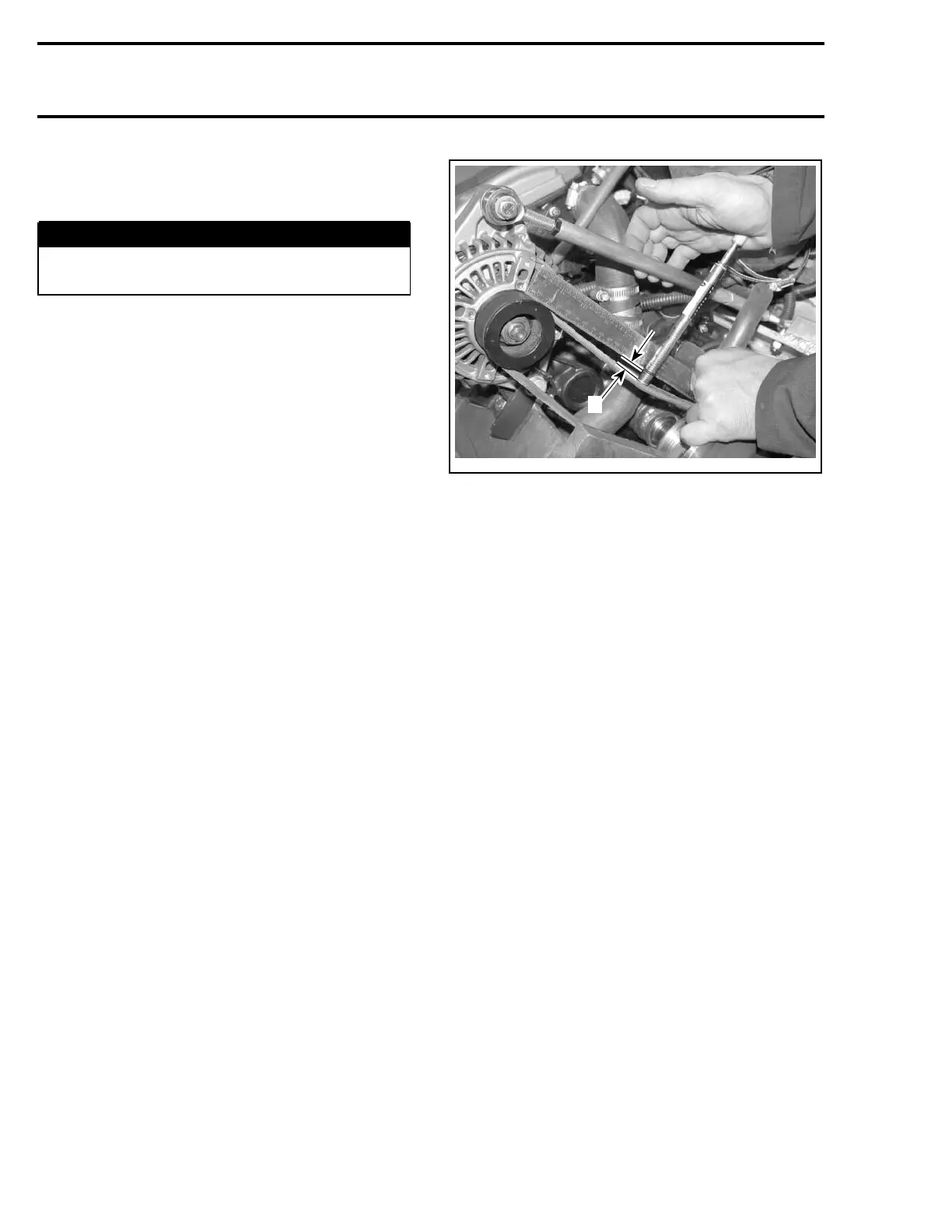
BELT TENSION ADJUSTMENT
Make sure alternator mounting bolt no. 5,retain-
ing bolt no. 6 and lock nuts no. 3 are loose.
Measure belt deflection when applying a down-
wardforceof2.27kg(5lb)onthebeltatmid
point between pulleys. Deflection must be 4 mm
(.157 in).
A34E0HA
A
A. Deflection
Turn adjustment rod no. 2 accordingly. Retighten
lock nuts no. 3, alternator mounting bolt no. 5
and retaining bolt no. 6, then recheck deflection.
Readjust if required.
250 Te m plat e

 Loading...