Section 05 ENGINE MANAGEMENT
Subsection 02 (COMPONENT INSPECTION AND ADJUSTMENT)
If wiring harness is defective, repair the connector
or replace the wiring harness between ECM ECU
connector and the ignition coil.
If wiring harness is good, test resistance of pri-
mary and secondary winding of ignition coil.
Resistance Test
CAUTION: Do not remove the ignition coil be-
fore disconnecting the connector, or the wires
will be damaged. Do not pry up ignition coil
with a screwdriver to avoid damage.
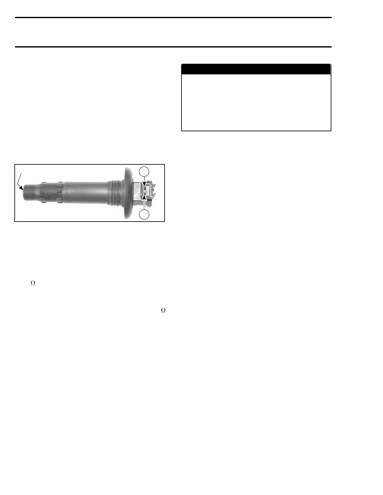
Remove ignition coil from spark plug.
1
R1503motr197A
2
1
1. Spark plug terminal
Using a multimeter, check the resistance in both
primary and secondary windings.
For primary winding check the resistance be-
tween terminals 1 and 2 of the ignition coil.
The resistance should be between 0.85 and
1.15
at 20°C(68°F).
For secondary winding check the resistance be-
tween terminal 1 and spark plug terminal.
The resistance should be between 9.5 and 13.5 k
at 20°C(68°F).
If the resistance of one of both windings is not
good, replace the defective ignition coil.
If the windings test good, try a new engine ECM
ECU.
NOTE: Prior to inserting the ignition coil to its lo-
cation, apply some silicone lubricant (P/N 293 600
041) around the seal area that touches the spark
plug hole. After installation, ensure the seal seats
properly with engine top surface.
WARNING
Always reconnect ignition coil cables at the
same spark plugs where they come from.
Otherwise, severe backfire may occur with
possible damage to exhaust system com-
ponents. The genuine wiring harness is
designed to prevent a cable mixing by using
different cable lengths.
TDC SETTING (TOP DEAD
CENTER)
The ECM is able to determine the exact position
of camshaft and crankshaft. That means that no
TDC setting has to be performed. It is used for
both injection and ignition timings.
ENGINE START SWITCH
VERIFICATION
If the vehicle fails to wake-up or start while turning
ON the ignition switch, check battery voltage and
fuses.
NOTE: Make sure the engine cut-out switch is not
in operation.
DESS SWITCH VERIFICATION
If 2 short beeps are not heard whenengine is
started, refer to DIAGNOSTIC PROCEDURES.
The following continuity tests can also be per-
formed using an ohmmeter.
Disconnect DESS post wires.
Tether Cord Cap Removed
Connect test probes to DESS post BLACK/WHITE
and BLACK wires. Measure resistance, there
should be NO continuity (open circuit).
Connect one test probe to the WHITE/GRAY wire
and the other test probe to the switch top termi-
nal. Measure resistance, it must be close to 0
ohm.
Connect one test probe to the BLACK/WHITE wire
and the other test probe to the DESS post ring.
Measure resistance, it must be close to 0 ohm.
206 Te m plat e

 Loading...