Section 08 REAR SUSPENSION
Subsection 01 (SC-10 III SUSPENSION)
A34F0DB
1
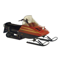
1. Panel
Remove rear arm top axle self-locking screws
no. 2 from chassis.
Lift rear of vehicle at least 1 m (3 ft).
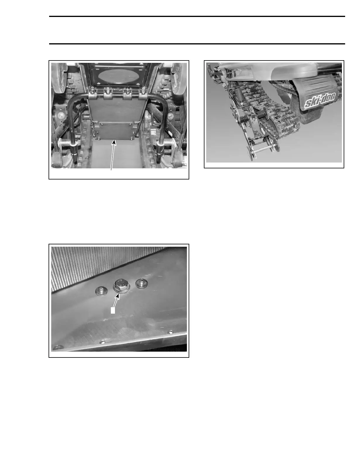
Remove both self-locking screws no. 1 retaining
front arm to tunnel. Inner screw is accessible
through the panel.
A34F0EA
1
1. Screw
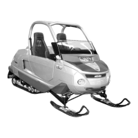
Remove suspension.
A34F0FA
Self-Locking Screws
CAUTION: These self-locking screws must al-
ways be replaced by new ones everytime they
are removed.
NOTE: To prevent axle from turning when un-
screwing self-locking screws nos. 1,2,3,4,5,6,
proceed as follows:
– Remove one self-locking screw then install a
10 mm shorter non-self-locking one in place.
Torque as specified in exploded view.
– Remove the opposite self-locking screw.
– Remove the temporary installed non-self-lock-
ing screw.
– If it doesn’t work, heat bolt head to melt thread
locker.
DISASSEMBLY AND ASSEMBLY
Inspect track thoroughly before reinstalling sus-
pension. Refer to TRACK.
Outer Bushing
At installation, hole of outer bushing no. 7 must
face adjustment screw.
Te m pla te 269
 Loading...