Section 05 ENGINE MANAGEMENT
Subsection 01 (OVERVIEW)
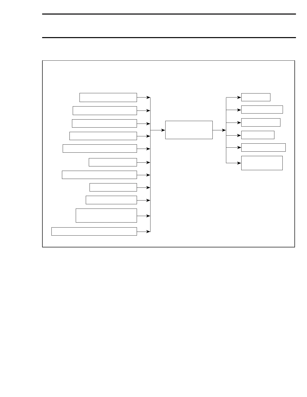
EMS — ENGINE MANAGEMENT FUNCTIONS
A34C1GS
1503 4-TEC CONTROL SYSTEM
INPUTS OUTPUTS
Idle bypass valve
Fuel injector
Ignition coil (3)
Starter solenoid
Fuel pump
Communication
port to VCM
Tip-over protection system (TOPS)
Digitally Encoded
Security System (DESS)
Battery voltage (BV)
Knock sensor (KS)
Throttle position (TPS)
Crankshaft position (CPS)
Coolant temperature (CTS)
Manifold air pressure (MAPS)
Oil pressure (OPS)
Oil tank pressure (OTPS)
Camshaft position (CAPS)
ENGINE CONTROL
MODULE
(ECM)
This engine management system controls both
the fuel injection and the ignition timing.
As shown in the CONTROL SYSTEM illustration,
the ECM ECU is the central point of the fuel injec-
tion system. It reads the inputs, makes computa-
tions, uses pre-determined parameters and sends
the proper signals to the outputs for proper engine
management.
The ECM ECU also stores the fault codes and gen-
eral information such as: operating conditions, ve-
hicle hours, serial numbers, customer and mainte-
nance information.
Electronic Fuel Injection
The ECM ECU reads the signals from different
sensors which indicate engine operating condi-
tions at milli-second intervals.
Signals from sensors are used by the ECM ECU
to determine the injection parameters (fuel maps)
required for optimum air-fuel ratio.
The CPS, the MATS, the MAPS and the TPS are
the primary sensors used to control the injection
and ignition timing. Other sensors (like tempera-
ture sensors, etc.) are used for secondary input.
NOTE: The OPS and OTPS sensors do not provide
control inputs to the ECM ECU. Their sole purpose
is to protect the engine components by emitting a
warning signal and/or a fault code in the event of
overheating or low oil pressure.
Ignition System
The ignition system is a digital inductive type. The
ECM ECU controls the ignition system parame-
ters, such as spark timing, duration and firing in
order to achieve the proper engine requirements.
Te m pla te 173
 Loading...