Section04ENGINE
Subsection 03 (EXHAUST SYSTEM)
1
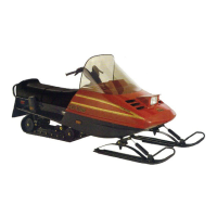
A34C0WA
1. O-ring in slot to hold the nut
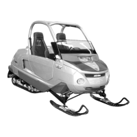
A34C0XA
1
1. 14 inch-drive extension with the modified socket
Remove the muffler.
Inspection
Inspect the muffler and connecting pipe paying
attention for cracks or other damage. Check
doughnut-shaped exhaust gaskets, coupling ar-
eas, heat shield, springs, spring brackets, rubber
mounts and tail pipe grommet. Replace any de-
fective part.
Installation
Installation is essentially the reverse of the re-
moval procedures. However, pay particular atten-
tion to the following:
Loosely install the muffler on its 4 rubber mounts.
Install the connecting pipe and its springs.
Tighten the muffler rubber mount nuts.
After installation, ensure there is no exhaust gas
leak when engine is running.
EXHAUST MANIFOLD
Removal
Remove muffler, then unbolt exhaust manifold.
Inspection
Inspect exhaust manifold paying attention for
cracks or other damage. Check contact surfaces.
Replace any defective part.
Inspect plane surfaces for warpage. Small defor-
mation can be corrected by grinding surface with
a fine sand paper. Install sand paper on a surface
plate and rub part against oiled sand paper.
Clean all metal components in a solvent.
Installation
Installation is essentially the reverse of removal
procedures. However, pay particular attention to
the following:
Install a new exhaust gasket.
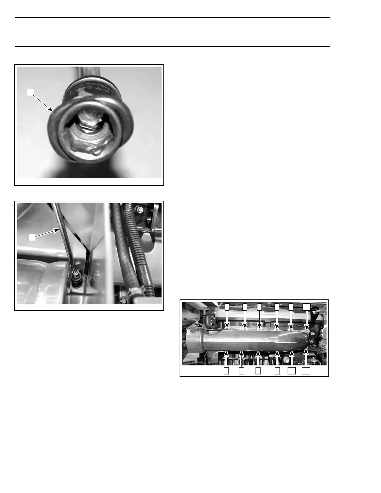
Apply Loctite 518 on threads of screws.
Torque screws to 10 N•m(88lbf•in) as per follow-
ing illustrated sequence. Repeat the procedure,
torquing screws again to 10 N•m(88lbf•in).
A34C0TA
7 5 1 3 9 11
12102468
After installation, ensure there is no exhaust gas
leak when the engine is running.
80 Te m plat e
 Loading...