Section 05 ENGINE MANAGEMENT
Subsection 02 (COMPONENT INSPECTION AND ADJUSTMENT)
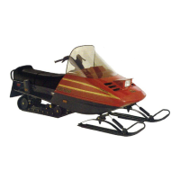
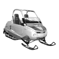
ENGINE WIRING HARNESS
R1503motr322A
1
2
11
14
15
9
7
6
3
4
8
13
10
12
16
5
4-TEC ENGINES
1. Ignition coils
2. BBV
3. OPS (hidden behind throttle body)
4. Idle bypass valve
5. Engine connector
6. Potentiometer
7. KS
8. Crank sensor
9. Connector housing
10. Temperature sensor
11.Injectors
12. WTS
13.CAPS
14. WTS
15. MAPS
16. OTPS
Resistance Test
Check continuity of the circuits according to the
wiring diagram in the WIRING DIAGRAMS section
of this manual.
If wiring harness is good, check the respective
sensor/actuator as described in this section.
Otherwise, repair the connectors, replace the
wiring harness or the ECM ECU/VCM as diag-
nosed.
Removal
Remove fuel rail cover.
Disconnect the wiring harness from all sensors/ac-
tuators.
Disconnect the ECM ECU connector from the
ECM ECU.
Cut all tie raps which are holding the wiring har-
ness in position.
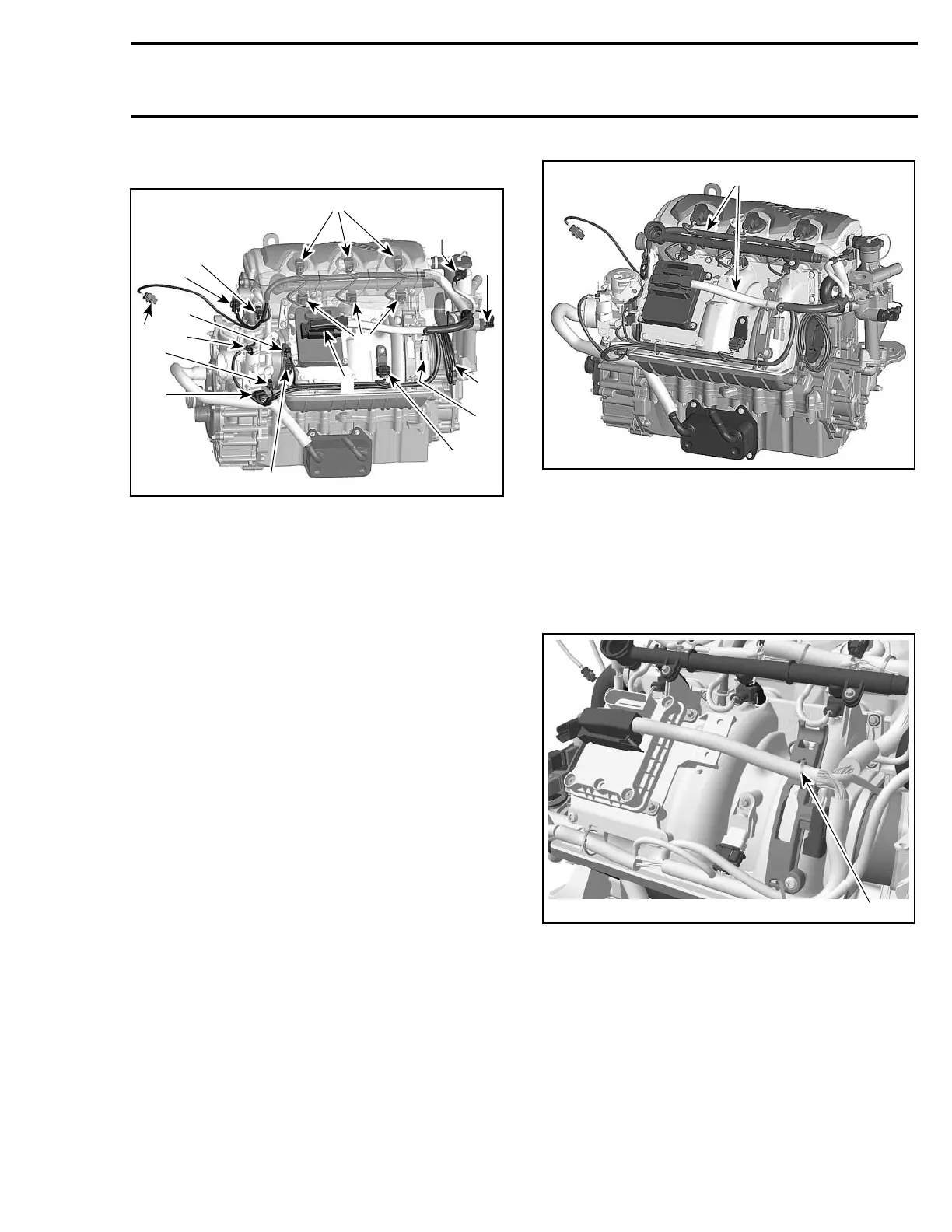
R1503motr323A
1
1. Wiring harness
Remove complete wiring harness.
Installation
First connect the ECM ECU connector A to the
ECM ECU and fix the harness on the wiring sup-
port with a locking tie.
1
R1503motr201A
1. Locking tie
Lead the cable bundle with the injector and igni-
tion coil connectors to the fuel rail and fix it also
by using 4 locking ties.
Te m pla te 193
 Loading...