Section04ENGINE
Subsection 09 (ENGINE BLOCK)
1
R1503motr13A
2
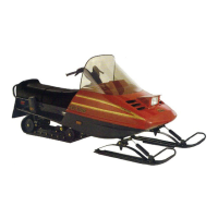
1. Micrometer
2. Crankshaft area for bushing
CRANKSHAFT JOURNAL DIAMETER mm (in)
NEW MINIMUM 49.91 mm (1.9650 in)
NEW MAXIMUM
50.01 mm (1.9689 in)
SERVICE LIMIT
49.88 mm (1.9637 in)
CRANKSHAFT JOURNAL RADIAL
CLEARANCE mm (in)
SERVICE LIMIT
0.07 mm (.0028 in)
Crankshaft Pin
Measure all crankshaft pin diameters. Compare to
in side diameter of connecting rod bushings (else-
where in this section).
R1503motr14A
12
1. Micrometer
2. Crankshaft pin area for bushing
CRANKSHAFT PIN DIAMETER mm (in)
NEW MINIMUM
45.032 mm (1.7729 in)
NEW MAXIMUM 45.048 mm (1.7735 in)
SERVICE LIMIT
45.029 mm (1.7728 in)
CRANKSHAFT PIN RADIAL CLEARANCE mm (in)
SERVICE LIMIT 0.09 mm (.0035 in)
Installation
For installation, reverse the removal procedure.
Pay attention to following details.
NOTE: Before installing the crankshaft, make
sure that the timing chain is on the crankshaft and
the chain guide has been installed first. Those
parts cannot be installed when the crankshaft is
in place.
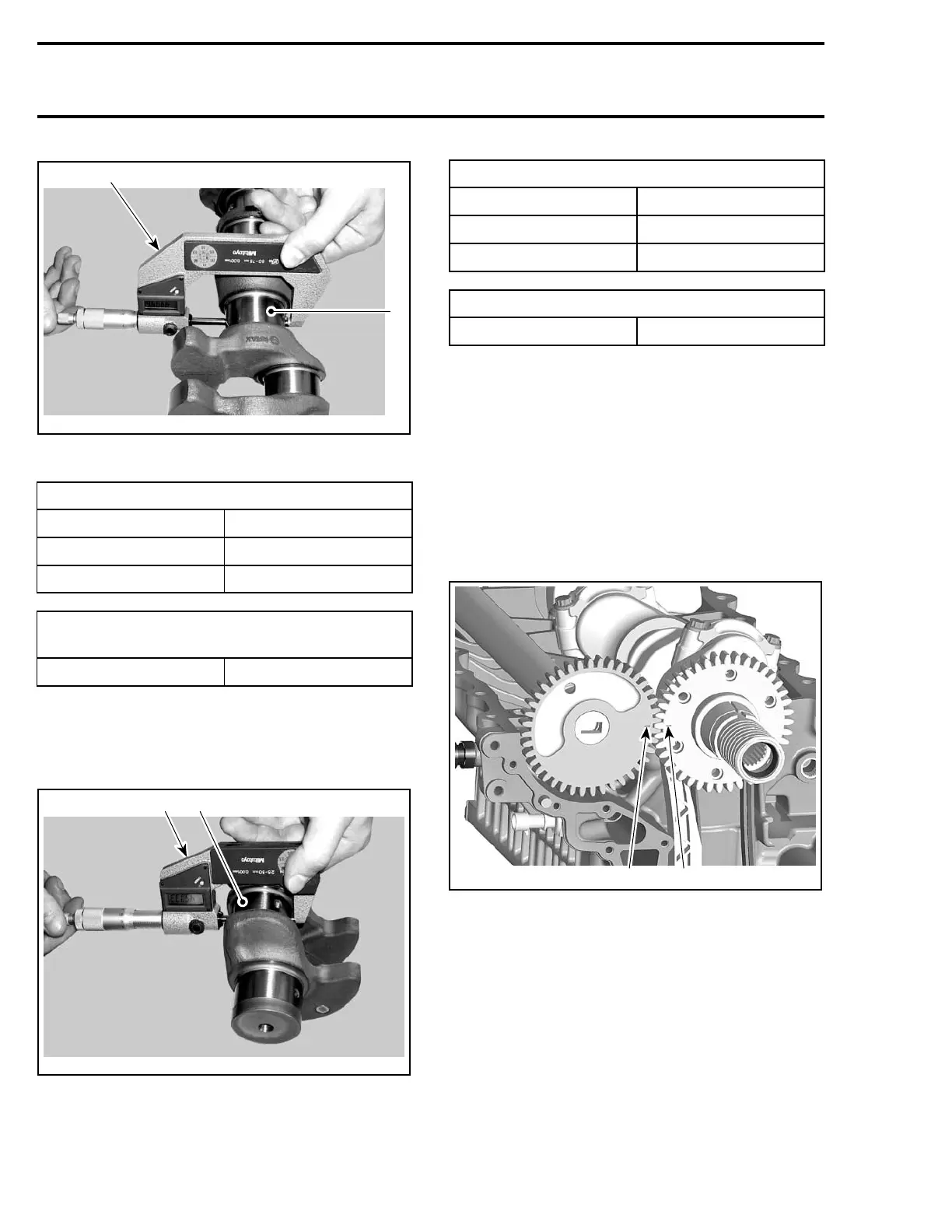
CAUTION: Crankshaft and balancer shaft
marks have to be aligned.
1
R1503motr307A
2
1. Mark on balancer shaft
2. Mark on crankshaft
For correct installation of the connecting rods refer
to CONNECTING ROD INSTALLATION elsewhere
in this section.
CAUTION: It is absolutely necessary to follow
this procedure. Otherwise severe engine dam-
age can occur.
148 Te m plat e

 Loading...