Section 05 ENGINE MANAGEMENT
Subsection 02 (COMPONENT INSPECTION AND ADJUSTMENT)
CIRCUIT NUMBER
(ECM ECU connector
“A”)
INJECTOR NUMBER
A-15
1
A-33 2
A-14 3
– If it does not read 12 V, check continuity of cir-
cuit as per following table. If it is good, try a
new VCM.
CIRCUIT NUMBER
(AMP connector #2)
INJECTOR NUMBER
2-16
1
2-17 2
2-18 3
Resistance Test
Reconnect the injector and disconnect the ECM
ECU connector A.
Remove tether cord cap and wait 15 seconds.
Disconnect engine connector.
CAUTION: Before unplugging engine connec-
tor, always remove tether cord cap and wait 15
seconds. Otherwise, damage to CAPS may oc-
cur.
Using a multimeter, check resistance value be-
tween terminals as follows.
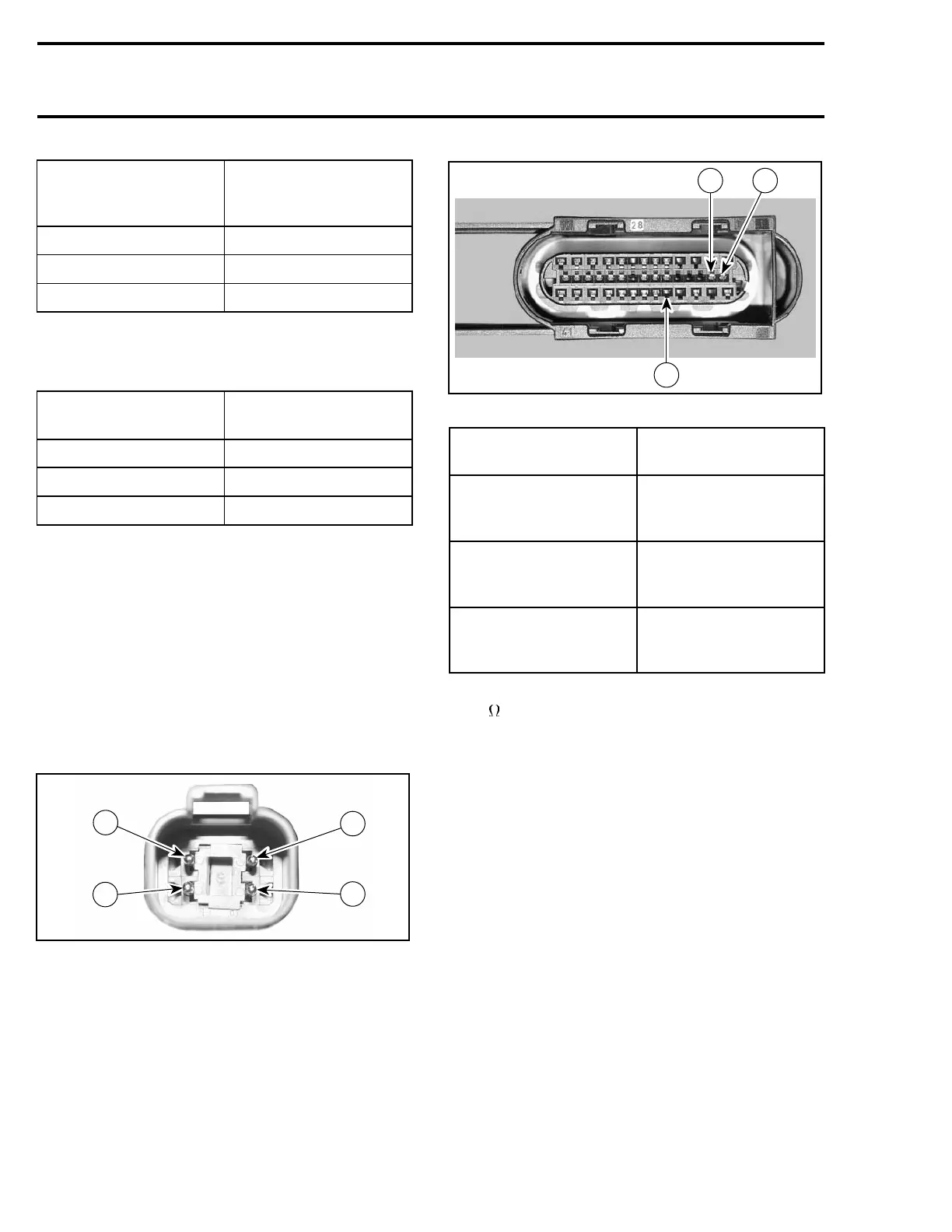
4
R1503motr192A
1
2
3
ENGINE CONNECTOR
R1503motr193A
15
33
14
ECM ECU CONNECTOR
COMPONENT TERMINAL
LOCATION
Fuel injector cylinder 1 1 (engine connector)
and A-15 (ECM ECU
connector)
Fuel injector cylinder 2 2 (engine connector)
and A-33 (ECM ECU
connector)
Fuel injector cylinder 3 3 (engine connector)
and A-14 (ECM ECU
connector)
The resistance should be between 11.4 and
12.6
.
If resistance value is correct, try a new ECM ECU.
Refer to ECM ECU REPLACEMENT procedures
elsewhere in this section.
If resistance value is incorrect, repair the wiring
harness/connectors or replace the wiring harness
between ECM ECU connector and fuel injector.
Fuel Injector Replacement
Removal
Before removing the injectors, the fuel rail has to
be removed from the engine. Refer to REMOVAL
in FUEL RAIL REPLACEMENT for the procedure.
190 Te m plat e
 Loading...