Section 06 TRANSMISSION
Subsection 02 (DRIVE PULLEY)
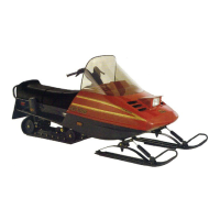
Position dowel tube split at the angle A.
A16D2PB
A
MODEL ANGLE (A)
TRA IV HD 45 ± 3°
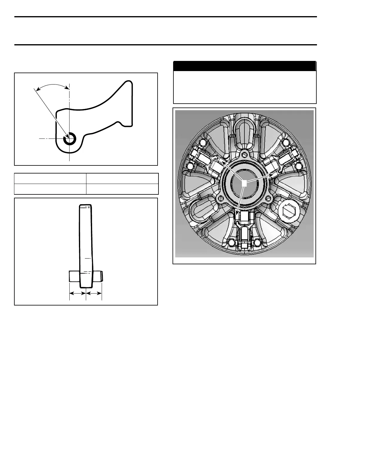
A16D09A
11
1. Equal distance
Torquescrewsto10N•m(89lbf•in).
9,10,11,13, Screw, Lever Axle,
Lever and Cotter Pin
Always install lever assemblies so that cotter pins
are on the left hand side. Besides install cotter pin
head on top when lever is sat at bottom of sliding
half. Bend cotter pin ends to sit perfectly against
lever.
WARNING
Whenever replacing centrifugal levers, al-
ways replace all 3 at the same time. Other-
wise, drive pulley misbalancing will occur
because of levers difference.
A34D08B
1
1. Head on top and on the left hand side
CAUTION: Lever assemblies must be installed
so that cotter pins are on the left hand side.
Torque screws no. 9 to 10 N•m(89lbf•in).
CAUTION: Lever ass’y and rollers must move
easily after installation.
5,6,14,18,19, Fixed Half, Sliding Half,
Cover Screw, Spring and Spring Cover
To install spring cover, use spring compressor
(P/N 529 035 524).
Assemble fixed and sliding halves. Note that fixed
halves have different cone angle. Match cone an-
gle with crankshaft.
Lift sliding half against spring cover and align
spring cover arrow with sliding half mark.
224 Te m plat e

 Loading...