MV-32/64 Multiviewer www.snellgroup.com Hardware Configuration
Issue 1 Rev 11 Page 134 © 2014 Snell Limited
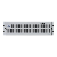
The example shown in Fig 91. illustrates what happens if, for example, a double width rear
connector is used for the card in slot one, but no video loop card is installed in slot two. The
next video card is in slot three, but due to the break in the signal path at slot two, it receives
no video from the card in slot one. This configuration is incorrect and will not work.
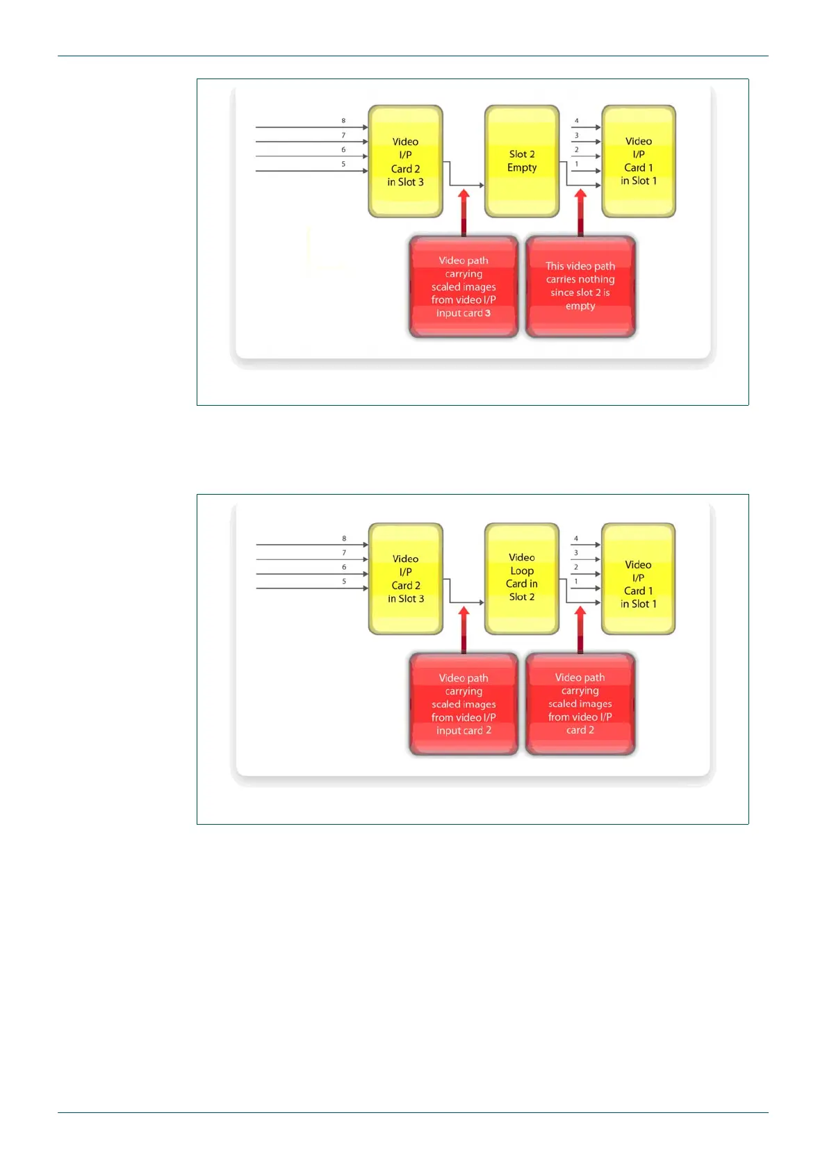
The example shown in Fig 92. illustrates how the video loop card allows the video path to
remain unbroken when using a dual width rear connector in slot 1.
Even if the last card in the chain has a double width rear, a video loop card is still required.
Another vital function of the video loop card is to pass the signals from the additional
connectors on the dual width rear module back to the card with which it is associated.
The double width rear modules have two PCBs that connect to the mid-plane within the
MV-32/MV-64 multiviewer.
Fig 91. Double Width Video Card in Slot 1 No Video Loop Card in Slot 2.
Fig 92. Double Width Video Card in Slot 1 Video Loop Card in Slot 2.