SN32F260 Series
32-Bit Cortex-M0 Micro-Controller
SONiX TECHNOLOGY CO., LTD Page 31 Version 1.5
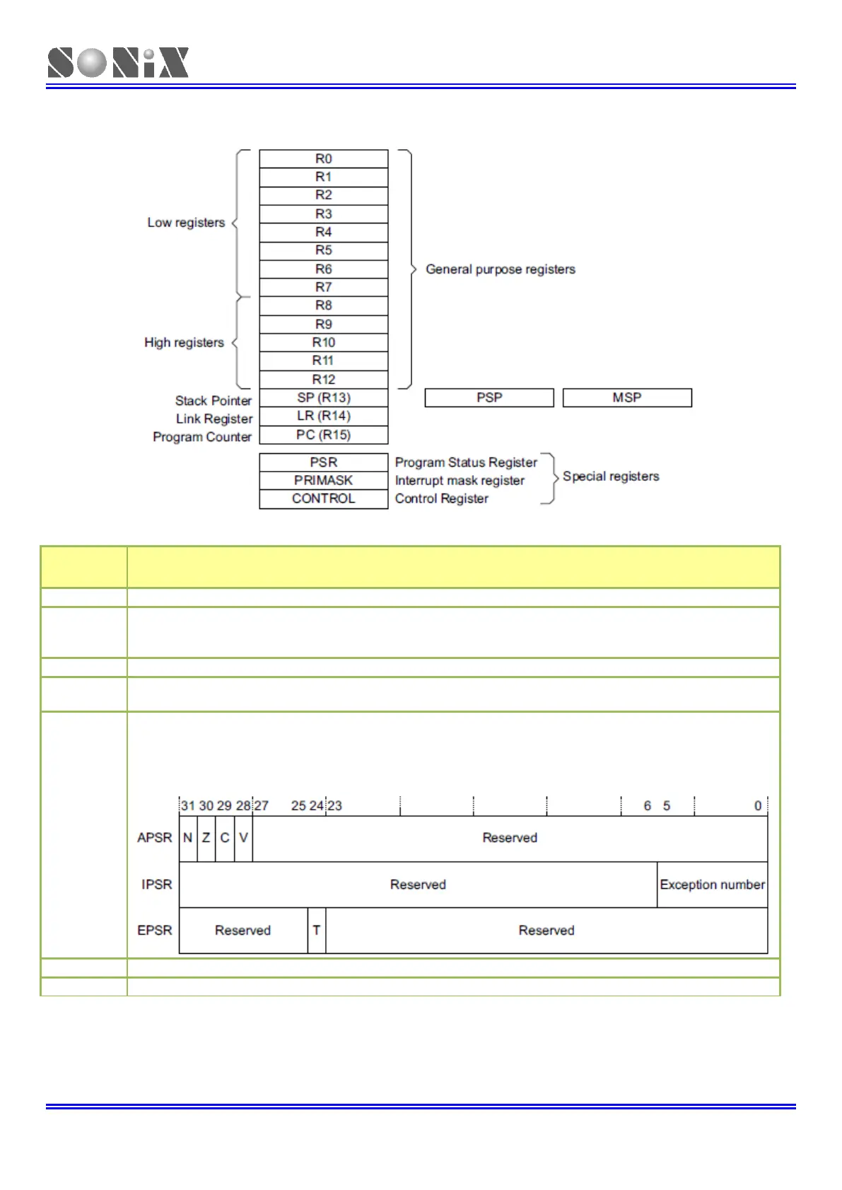
2.6 CORE REGISTER OVERVIEW
Description (Refer to Cortex-M0 Spec)
General-purpose registers for data operations.
The Stack Pointer (SP). In Thread mode, the CONTROL register indicates the stack pointer to use,
Main Stack Pointer (MSP) or Process Stack Pointer (PSP)
On reset, the processor loads the MSP with the value from address 0x00000000.
The Link Register (LR). It stores the return information for subroutines, function calls, and exceptions.
The Program Counter (PC). It contains the current program address.
On reset, the processor loads the PC with the value of the reset vector, at address 0x00000004.
The Program Status Register (PSR) combines:
• Application Program Status Register (APSR)
• Interrupt Program Status Register (IPSR)
• Execution Program Status Register (EPSR).
These registers are mutually exclusive bit fields in the 32-bit PSR.
The PRIMASK register prevents activation of all exceptions with configurable priority.
The CONTROL register controls the stack used when the processor is in Thread mode.