SN32F260 Series
32-Bit Cortex-M0 Micro-Controller
SONiX TECHNOLOGY CO., LTD Page 72 Version 1.5
Capture on CT16Bn_CAP0 rising edge: a sequence of 0 then 1 on
CT16Bn_CAP0 will cause CAP0 to be loaded with the contents of TC.
0: Disable.
1: Enable.
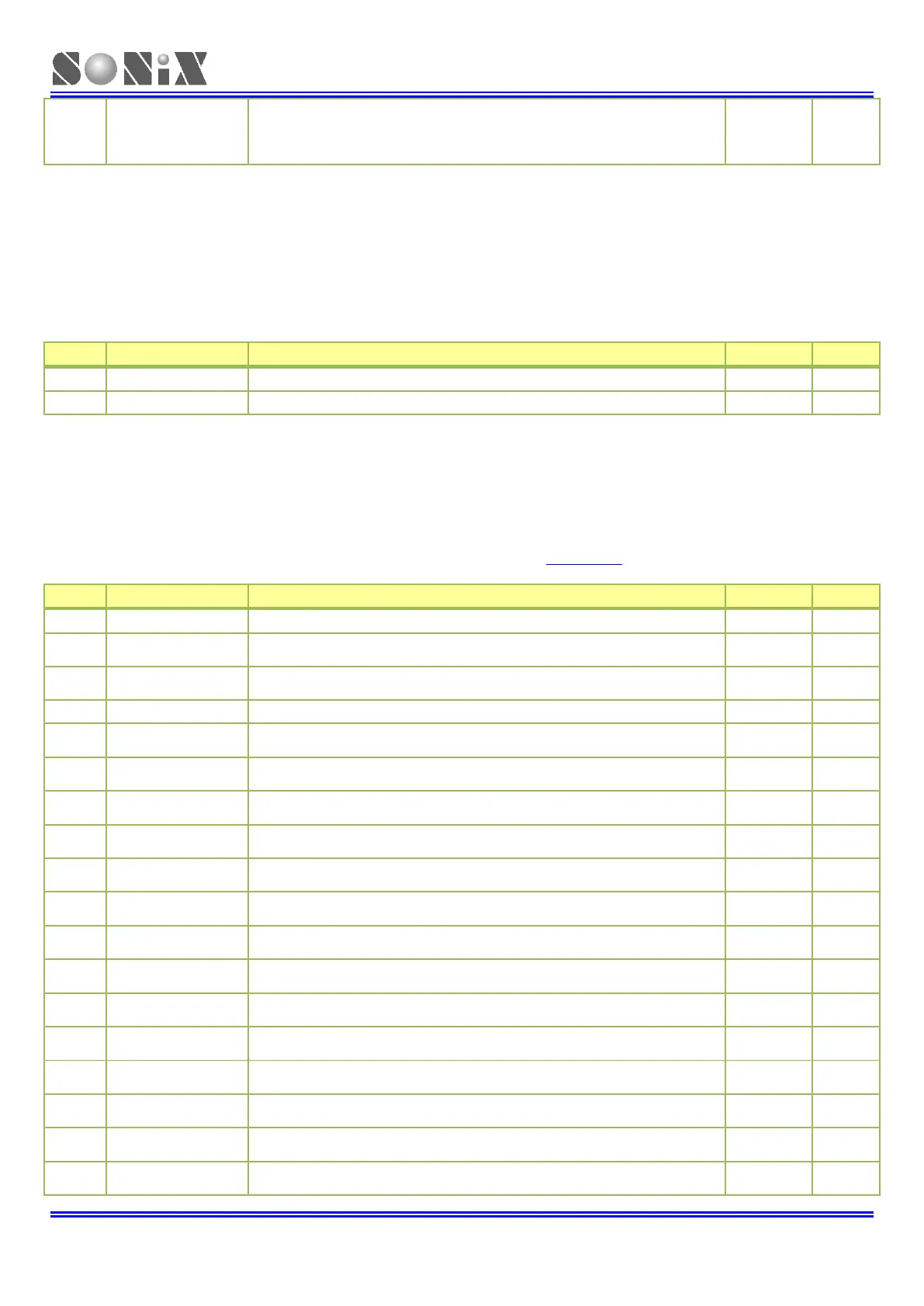
6.7.13 CT16Bn Capture 0 register (CT16Bn_CAP0) (n=0)
Address Offset: 0x84
Each Capture register is associated with a device pin and may be loaded with the counter/timer value when a specified
event occurs on that pin. The settings in the Capture Control register determine whether the capture function is
enabled, and whether a capture event happens on the rising edge of the associated pin, the falling edge, or on both
edges.
Timer counter capture value.
6.7.14 CT16Bn External Match register (CT16Bn_EM)(n=1)
Address Offset: 0x88
The External Match register provides status of CT16Bn_PWM [22:0]. If the match outputs are configured as PWM
output, the function of the external match registers is determined by the PWM rules.
When the TC and MR22 are equal, this bit will act according to EMC22
bits, and also drive the state of CT16Bn_PWM22 output.
When the TC and MR21 are equal, this bit will act according to EMC21
bits, and also drive the state of CT16Bn_PWM21 output.
When the TC and MR19 are equal, this bit will act according to EMC19
bits, and also drive the state of CT16Bn_PWM19 output.
When the TC and MR18 are equal, this bit will act according to EMC18
bits, and also drive the state of CT16Bn_PWM18 output.
When the TC and MR17 are equal, this bit will act according to EMC17
bits, and also drive the state of CT16Bn_PWM17 output.
When the TC and MR16 are equal, this bit will act according to EMC16
bits, and also drive the state of CT16Bn_PWM16 output.
When the TC and MR15 are equal, this bit will act according to EMC15
bits, and also drive the state of CT16Bn_PWM15 output.
When the TC and MR14 are equal, this bit will act according to EMC14
bits, and also drive the state of CT16Bn_PWM14 output.
When the TC and MR13 are equal, this bit will act according to EMC13
bits, and also drive the state of CT16Bn_PWM13 output.
When the TC and MR12 are equal, this bit will act according to EMC12
bits, and also drive the state of CT16Bn_PWM12 output.
When the TC and MR11 are equal, this bit will act according to EMC11
bits, and also drive the state of CT16Bn_PWM11 output.
When the TC and MR10 are equal, this bit will act according to EMC10
bits, and also drive the state of CT16Bn_PWM10 output.
When the TC and MR9 are equal, this bit will act according to EMC9 bits,
and also drive the state of CT16Bn_PWM9 output.
When the TC and MR8 are equal, this bit will act according to EMC8 bits,
and also drive the state of CT16Bn_PWM8 output.
When the TC and MR7 are equal, this bit will act according to EMC7 bits,
and also drive the state of CT16Bn_PWM7 output.
When the TC and MR6 are equal, this bit will act according to EMC6 bits,
and also drive the state of CT16Bn_PWM6 output.