SN32F260 Series
32-Bit Cortex-M0 Micro-Controller
SONiX TECHNOLOGY CO., LTD Page 54 Version 1.5
5.3 GPIO REGISTERS
Base Address: 0x4004 4000 (GPIO 0)
0x4004 6000 (GPIO 1)
0x4004 8000 (GPIO 2)
0x4004 A000 (GPIO 3)
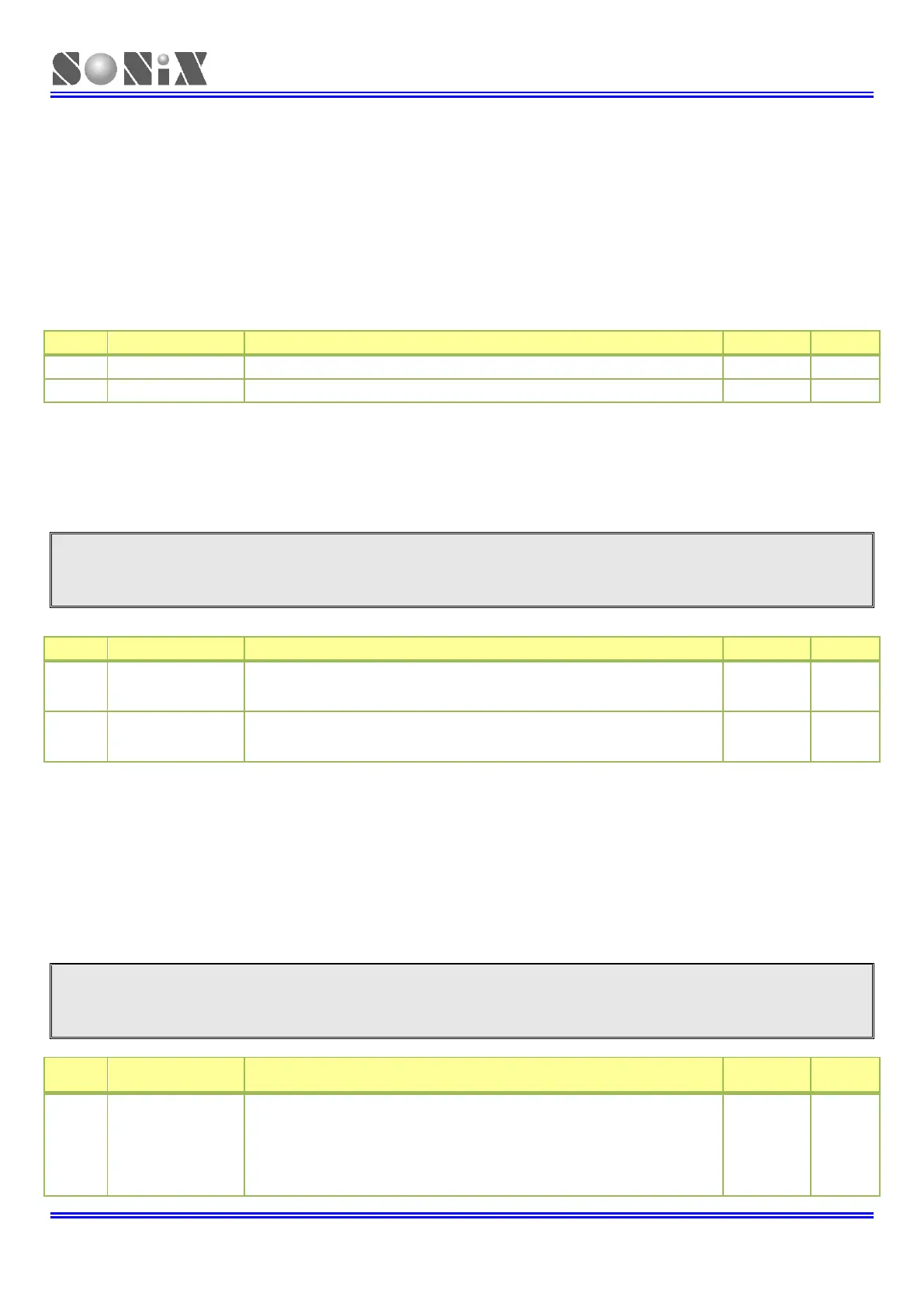
5.3.1 GPIO Port n Data register (GPIOn_DATA) (n=0,1,2,3)
Address offset: 0x00
Input data (read) or output data (write) for Pn.0 to Pn.15
5.3.2 GPIO Port n Mode register (GPIOn_MODE) (n=0,1,2,3)
Address offset: 0x04
Note: HW will switch I/O Mode directly when Specific function (Peripheral) is enabled, not through
GPIOn_MODE register.
Driving/Sinking current selection (x = 0 to 15)
0: Typical 10mA
1: Typical 20mA
Selects pin x as input or output (x = 0 to 15)
0: Pn.x is configured as input
1: Pn.x is configured as output.
5.3.3 GPIO Port n Configuration register (GPIOn_CFG) (n=0,1,2,3)
Address offset: 0x08
Reset value: n=0 0xAAAA AAAA
n=1 0x0000 0AAA
n=2 0x002A AAAA
n=3 0x0002 AAAA
Note: HW will switch I/O Mode directly when Specific function (Peripheral) is enabled, not through
GPIOn_MODE register.
Configuration of Pn.15
00: Pull-up resistor enabled.
01: Reserved.
10: Inactive. (no pull-up resistor enabled, Schmitt trigger enabled).
11: Inactive. (no pull-up resistor enabled, Schmitt trigger disabled, Data
register keep low)