SN32F260 Series
32-Bit Cortex-M0 Micro-Controller
SONiX TECHNOLOGY CO., LTD Page 75 Version 1.5
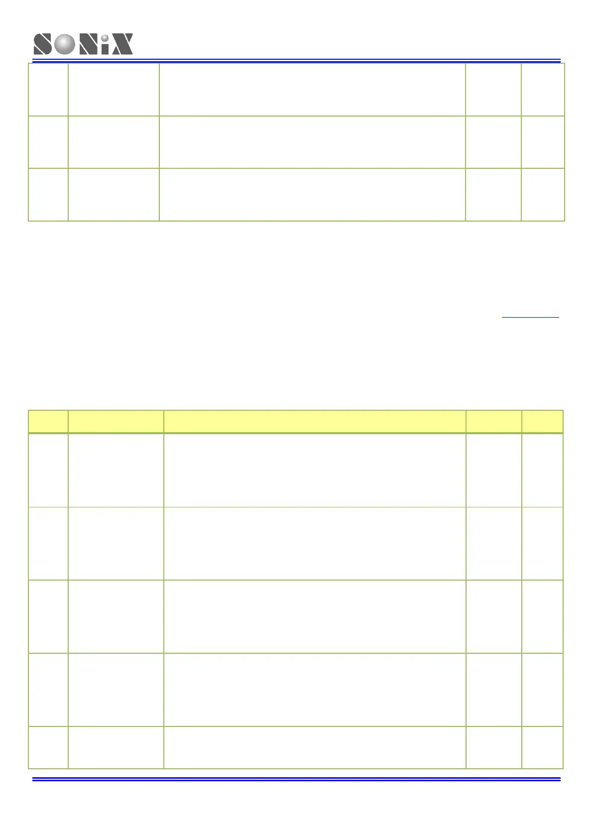
Determines the functionality of CT16Bn_PWM18.
00: Do Nothing.
01: CT16Bn_PWM18 pin is LOW.
10: CT16Bn_PWM18 pin is HIGH.
11: Toggle CT16Bn_PWM18 pin.
Determines the functionality of CT16Bn_PWM17.
00: Do Nothing.
01: CT16Bn_PWM17 pin is LOW.
10: CT16Bn_PWM17 pin is HIGH.
11: Toggle CT16Bn_PWM17 pin.
Determines the functionality of CT16Bn_PWM16.
00: Do Nothing.
01: CT16Bn_PWM16 pin is LOW.
10: CT16Bn_PWM16 pin is HIGH.
11: Toggle CT16Bn_PWM16 pin.
6.7.17 CT16Bn PWM Control register (CT16Bn_PWMCTRL) (n=1)
Address Offset: 0x94
The PWM Control register is used to configure the match outputs as PWM outputs. Each match output can be
in-dependently set to perform either as PWM output or as match output whose function is controlled by CT16Bn_EM
register.
For each timer, a maximum of 4 single edge controlled PWM outputs can be selected on the CT16Bn_PWMCTRL [3:0]
outputs. One additional match register determines the PWM cycle length. When a match occurs in any of the other
match registers, the PWM output is set to HIGH. The timer is reset by the match register that is configured to set the
PWM cycle length. When the timer is reset to zero, all currently HIGH match outputs configured as PWM outputs are
cleared.
PWM15 output.
00: PWM mode 1.
PWM15 is 0 when TC<MR15 during Up-counting period.
01: PWM mode 2.
PWM1 5 is 1 when TC<MR15 during Up-counting period.
10: PWM15 is forced to 0.
11: PWM15 is forced to 1.
PWM14 output.
00: PWM mode 1.
PWM14 is 0 when TC<MR14 during Up-counting period.
01: PWM mode 2.
PWM14 is 1 when TC<MR14 during Up-counting period.
10: PWM14 is forced to 0.
11: PWM14 is forced to 1.
PWM13 output.
00: PWM mode 1.
PWM13 is 0 when TC<MR13 during Up-counting period.
01: PWM mode 2.
PWM13 is 1 when TC<MR13 during Up-counting period.
10: PWM13 is forced to 0.
11: PWM13 is forced to 1.
PWM12 output.
00: PWM mode 1.
PWM12 is 0 when TC<MR12 during Up-counting period.
01: PWM mode 2.
PWM12 is 1 when TC<MR12 during Up-counting period.
10: PWM12 is forced to 0.
11: PWM12 is forced to 1.
PWM11 output.
00: PWM mode 1.
PWM11 is 0 when TC<MR11 during Up-counting period.
01: PWM mode 2.