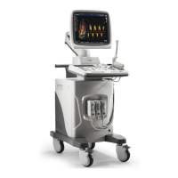
SSI-6000/SSI-5800/SSI-5500/SSI-5500BW
Digital Color Doppler Ultrasound System
• use the LEFT/RIGHT keys to adjust the output power of the transducer.
Remark:
• The acoustic output power in the CDI mode is displayed on the screen at the
Color Image Info area (PWR).
6.3.9 Baseline
BASELINE
Shifting the baseline increases the velocity range in one direction, the zero position
also moves as a result. The maximum velocities in both directions are displayed at
the ends of the Spectral Wedge (15, Figure 2.2).
• go to the CDI menu (Figure 6.2), highlight BASELINE.
• use the LEFT/RIGHT keys to adjust the amount of the baseline shift.
6.3.10 Sector Width and Position
SEC.WIDTH
SEC.POS
Sector width and position are the same as those in the B mode, refer to Section
5.3.11: only this time you need to access the CDI menu (Figure 6.2) instead of the
B mode menu.
6.3.11 B Reject
B REJECT
Sets the display priorities of the color and 2D grayscale pixels. Larger B Reject
value suppresses more grayscale pixels.
The B Reject value is adjustable in the real time mode as well as the freeze mode.
• go to the context menu, highlight B REJECT.
• use the LEFT/RIGHT keys to adjust the B Reject value.
6.3.12 CDI Frequency
FREQUENCY
The CDI mode frequency controls the transmit frequency.
Higher frequency delivers better display of low flow velocities, but the penetration
depth is reduced.
Lower frequency delivers better display of high flow velocities, but the penetration
depth is increased.
• highlight FREQUENCY at the context menu.
• use the LEFT/RIGHT keys to adjust the frequency value.
P/N: 4701-0061-01B
6-5

 Loading...