Page 16 MZC-88 Installation Instructions
EPR-1.0 EZ-PAD RELAY MUTING MODULE
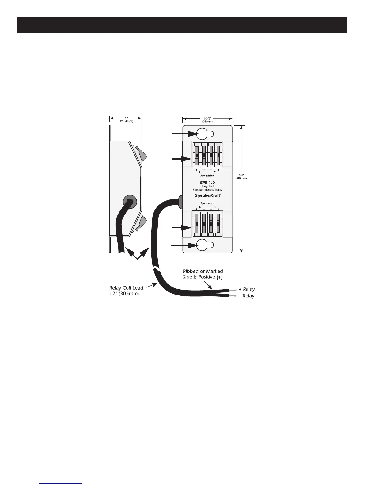
Figure 6.
EPR-1.0 EZ-Pad Relay Features
1. MOUNTING HOLES — Two, keyholes, use these holes to mount the EPR-1.0 to any flat surface (usually to the studding
in the wall behind the EZ-Pad or the in-wall speakers).
2. “
AMPLIFIER” EZ-CONNECT TERMINALS — Four, spring-loaded terminals connect to the amplifier L & R speaker
level output terminals. WIRE GAUGE: 14 to 28 AWG.
3. “
SPEAKERS” EZ-CONNECT TERMINALS — Four, spring-loaded terminals connect to the L & R terminals on the room
speakers. WIRE GAUGE: 14 to 28 AWG.
4. RELAY COIL LEADS — This 12" (305mm) 2-conductor lead connects to the +Relay and –Relay terminals on the back
of the EZ-Pad. It can be extended to any length required (2000’ with 24 AWG wire). Maintain proper polarity. When the
designated MUTE key on the EZ-Pad is pressed, the EPR-1.0 relay opens, thus muting the audio. The selected source but-
ton on the EZ-Pad will blink at a slow rate to indicate the muted condition.
The EPR-1.0 EZ-Pad Speaker Muting Relay Module allows local speaker muting in any room with an EZ-Pad. Example: An
MZC-88 Zone PRE-OUT feeding a multi-channel amplifier for sub-zone expansion. Each of the additional ‘rooms’ would utilize
one stereo pair speaker-level output from the multi-channel amp, have an EZ-Pad for system and source control and each
keypad would have an EPR-1.0 to mute the local speakers. All rooms in the zone would have the same ON/OFF status and
play the same source. Individual room mute could then be controlled either from a keypad or an appropriately programmed
IR Remote.

 Loading...