Page 40 MZC-88 Installation Instructions
EXPANDED SYSTEMS
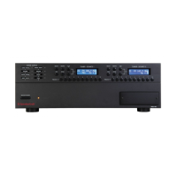
Up to four MZC-88s can be “daisy-chained” together to create systems with up to 32 Zones. The first MZC-88 in the chain is
referred to as the Master and the subsequent MZC-88’s are referred to as Slaves. System Zone numbers correspond to the
MZC-88 Master and Slaves as follows:
MZC-88 Master Zones 1-8
MZC-88 Slave 1 Zones 9-16
MZC-88 Slave 2 Zones 17-24
MZC-88 Slave 3 Zones 25-32
A CAT-5/RJ45 cable must be used to loop system function data between the MZC-88 Master and Slaves.
Each MZC-88 requires a dedicated KCM-1.0 for associated zone keypad and IR receiver connections.
MZC-88’S AND MZC-66’S CANNOT BE DAISYCHAINED TOGETHER IN THE SAME SYSTEM!
All External Common Source Components get connected to the Source Inputs on the Master. The external source audio and
video signals are then looped from the Master to the Slave MZC-88’s for A/V distribution to expanded zones. External Source
IR control is looped in a reverse direction from the highest numbered Slave back to the Master and output from the Master to
the external sources via IR emitters.
Each MZC-88 requires a dedicated HED-1.0 Antenna Head Amp for the dual internal tuners. All MZC-88 Zone Tuner Presets
must be configured individually. Programming the Master does not set the Slave presets. This increases the overall flexibility of
the system by allowing each zone to have up to 10 different preset stations per tuner.
Phone/Video Paging A/V signals require an audio/video distribution amp to feed the telephone audio and/or camera video
signals to each of the MZC-88 Master and Slaves. The Doorbell/Status Trigger Inputs must be looped to trigger all MZC Master
and Slave Page Inputs.
The Common IR Out and Common Status Out jacks must be looped for control of common IR or voltage controlled devices.
INSTALLATION
Additional space should be allocated for installation of each additional MZC-88. Leave at least 3-4 inches above and below
each Controller for proper air flow for cooling. Mounting MZC-88s at the top of an equipment cabinet is recommended to
reduce source components exposure to excess heat. Use cooling fans when necessary.
CONNECTIONS AND CONFIGURATION
KEYPADS
1. Connect a KCM-1.0 to each MZC-88.
2. Connect Keypads and IR receivers to the appropriate KCM-1.0 EZ-Pad Zone terminals. Maintain proper polarity and check
all connections prior to powering up the system.
AUDIO/VIDEO-External Common Source Components
1. Connect one, quality, RCA-RCA A/V patch cable from each external source component to the appropriate Source Input
on the MZC-88 MASTER.
2. Connect one, quality, RCA-RCA A/V patch cable from the LOOP A/V OUT on the MZC-88 MASTER to the same source
number A/V Input on the next MZC-88 Slave in the chain. (Master to Slave 1, Slave 1 to Slave 2, etc.)
3. Repeat steps 1-2 for all external common source components.
IR-External Common Source Components
1. Connect one 3.5mm mini-mini patch cable from the IR OUT of the last Slave, (Slave 3 if using 4 MZC-88s) to the same
source number IR LOOP jack on the next MZC-88 in the chain (Slave 3 to Slave 2, Slave 2 to Slave 1, Slave 1 to Mas-
ter) for each external common source component to be controlled via IR.
2. Connect an IR emitter to the IR OUT on the Master and attach to the appropriate source component over the IR eye
of that component.

 Loading...