Service Information
87
ZOOMR OPTION CONTROL BAR POTENTIOMETER REPLACEMENT
Required Tools:
T27 Torx 1/2” Box End Wrench #2 Phillips Screwdriver
Wire Cutters Small Flat Blade Screwdriver 5/16” Nut Driver
Replacement Procedure:
1. Raise the litter and the head end to the full up position.
2. Remove the head board from the bed.
3. Unplug the power cord from the wall socket and push the battery power on/off switch to the “OFF” posi-
tion.
4. Using a 5/16” nut driver, remove the screw holding the power cord clamp to the bumper weldment and
remove the clamp from the bumper.
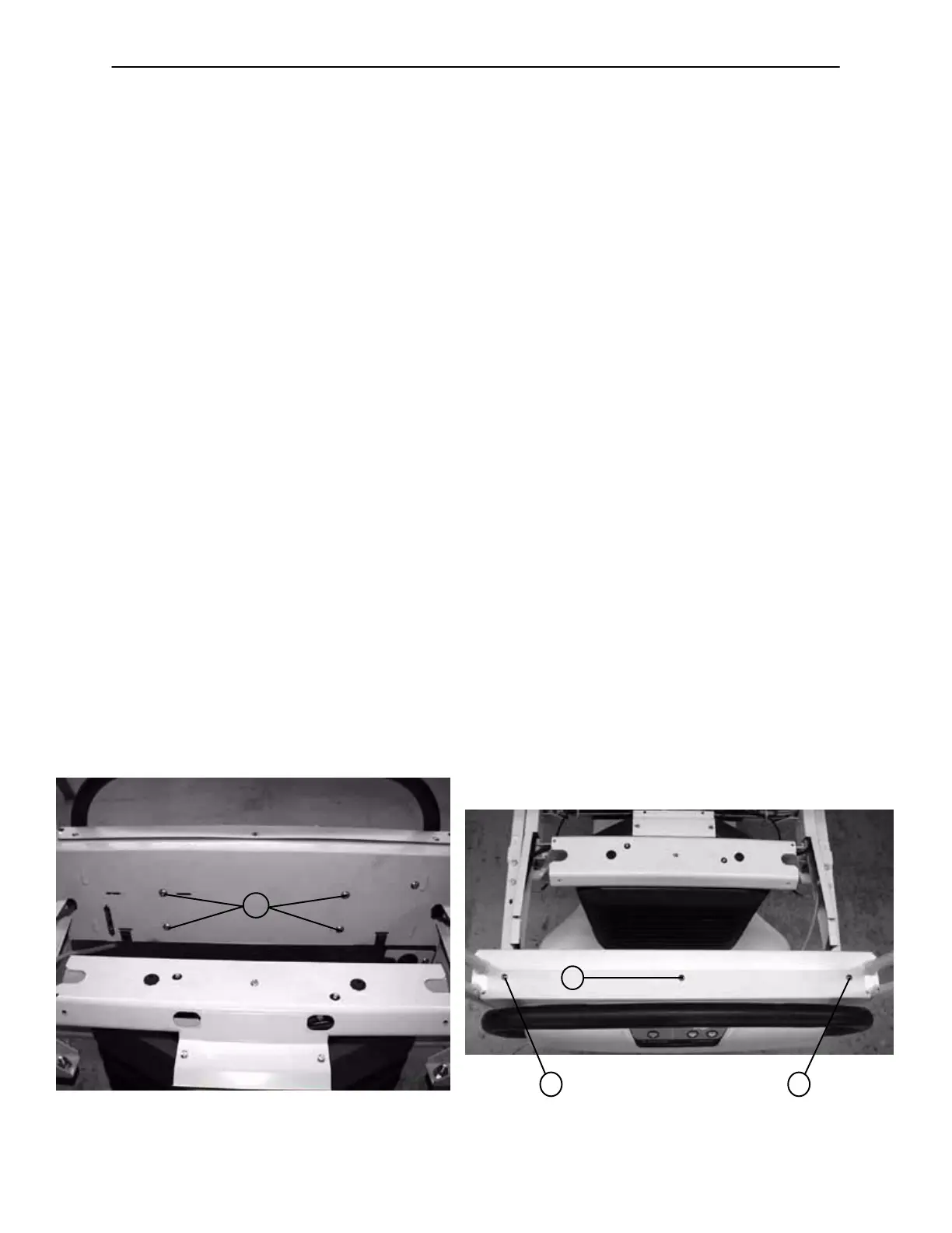
5. Using a T27 Torx, remove the four bolts (A) at the head end of the bed holding the control bar mounting
bracket to the head end (see Figure 1).
6. Using a #2 Phillips screwdriver, remove the three screws (B) holding the control bar cover to the head
end of the bed (see Figure 2).
7. Standing at the head end, pull the control bar toward you and fold down the control bar mounting bracket.
8. Using a 1/2” wrench, remove the nut holding the potentiometer to the mount. Using wire cutters, cut the
wire ties. Unplug the pot cable from the CPU display board and remove the pot.
9. Install the new potentiometer. Using a small flat blade screwdriver, turn the pot shaft clockwise until it
stops. Turn it back counterclockwise 1/2 turn.
10. After the new pot has been installed, the potentiometer “burn−in” procedure must be performed (see
page 88).
11. After performing the “burn−in” procedure, reverse steps 1 − 7 to reassemble the bed.
12. Test all functions before returning the unit to service.
FIGURE 1
A
FIGURE 2
B
B B

 Loading...