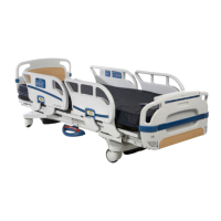
Bed Circuit Boards
46
CPU BOARD − 3002−407−950
CABLE
LOCATION
VOLTAGE POSITIVE
LEAD
NEGATIVE
LEAD
DESCRIPTION
W +12 VDC Pin 1 Pin 4 or 5 Relays & Siderails Light Volt-
age
W +5 VDC Pin 2 & 3 Pin 4 or 5 +5 VDC from Power Supply
W −12 VDC Pin 6 Pin 4 or 5 Relays & Siderails Light Volt-
age
J +5 VDC Pin 4 Pin 2 +5 VDC for Head Lift Pot
J 0 − 5 VDC Pin 3 Pin 2 Head Lift Pot Wiper
C +5 VDC Pin 1 Pin 2 +5 VDC for Foot Lift Pot
C 0 − 5 VDC Pin 3 Pin 2 Foot Lift Pot Wiper
GG 0 VAC w/o Switch 110
VAC w/Switch
Pin 2
Purple
Pin 1 Blue Gatch Up
GG 0 VAC w/o Switch 110
VAC w/Switch
Pin 3 Red Pin 1 Blue Gatch Down
CC 0 VAC w/o Switch 160
VAC w/Switch
Pin 1 Black Pin 3 Red Fowler Up
CC 0 VAC w/o Switch 120
VAC w/Switch
Pin 2 White Pin 3 Red Fowler Down
O 110 VAC Pin 1 Pin 2 Line Voltage to Bed
N 0 VAC w/o Switch 120
VAC w/Switch
Pin 3 Black Pin 1 White Head Lift Down
N 0 VAC w/o Switch 120
VAC w/Switch
Pin 6 Red Pin 1 White Head Lift Up
G 0 VAC w/o Switch 120
VAC w/Switch
Pin 3 Black Pin 1 Red Foot Lift Down
G 0 VAC w/o Switch 120
VAC w/Switch
Pin 6 White Pin 1 Red Foot Lift Up
 Loading...
