147 © STULZ GmbH – all rights reserved EN/01.2019/G22
ec tower technical manual
1
2
3
10
4
8
9
6
7
4
5
17
16
15
X
Y
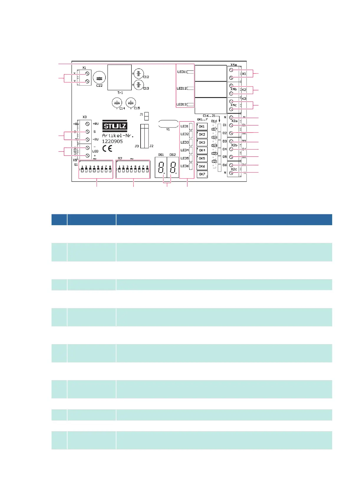
No. Designation Description
1
X4a-K1
Alarm signal,
voltage-free, up to 230V AC / 130V DC / 0.5 A / NO, can be inverted with S26
2
X4b-K2
Compressor signal or operating signal,
voltage-free, up to 230V AC / 130V DC / 0.5 A / NO, can be inverted with S26
3
X4c-K3
Defrosting signal, heating signal, window contact signal, or temperature limit alarm,
voltage-free, up to 230V AC / 130V DC / 0.5 A / NO, can be inverted with S26
4
X2a-N, X2c-N Common neutral wire for digital inputs D1 to D6
5
X2a-D1
Assignment is program-specific,
20VDC to 130V DC or 24VAC to 230V AC
6
X2a-D2
Assignment is program-specific,
20VDC to 130V DC or 24VAC to 230V AC
7
X2b-D3
Assignment is program-specific,
20VDC to 130V DC or 24VAC to 230V AC
8
X2b-D4
Assignment is program-specific,
20VDC to 130V DC or 24VAC to 230V AC
9
X2b-D5
Assignment is program-specific,
20VDC to 130V DC or 24VAC to 230V AC
10
X2c-D6
Assignment is program-specific,
20VDC to 130V DC or 24VAC to 230V AC
11
LED1 to LED6 Status display of digital inputs D1 to D6
12
DS1, DS2 7-segment display
13
S2 DIP switch for selecting program-dependent functions and the 7-segment display
14
S1
DIP switch for setting the relevant program, and also for setting the installed outdoor unit model in
Program 8
3.2 InterfaceIIIk connection assignment