154 EN/01.2019/G22 © STULZ GmbH – all rights reserved
ec tower technical manual
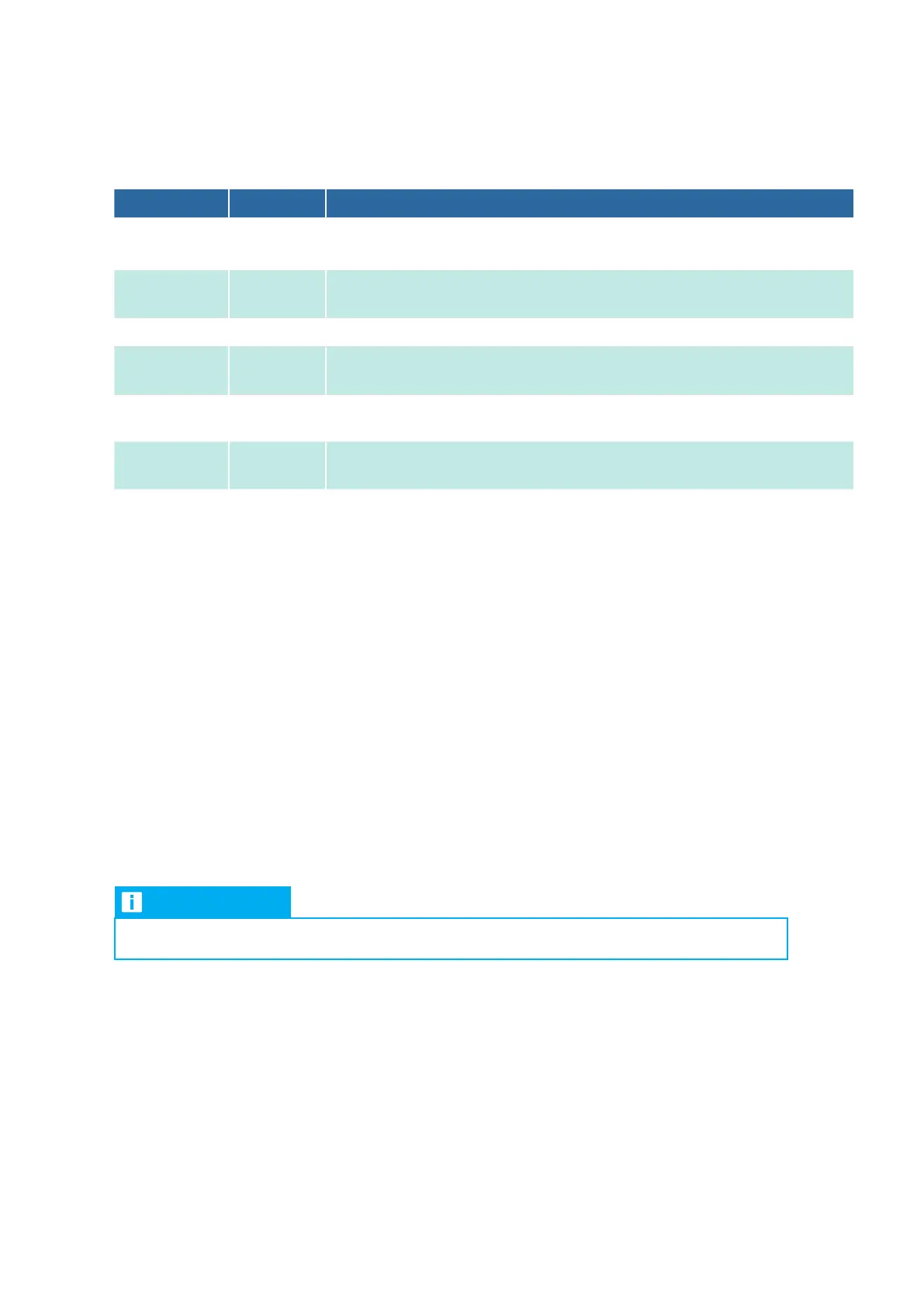
6.2.2 Setting the functions for Program 8 on DIP switch S2
The following table lists the functions for Program 8 in brief. See „4. InterfaceIIIk functions“ for a detailed
description of the functions.
DIP switch Status Function
S21
ON
OFF
Interface
IIIk is master
Interface
IIIk is slave
S22
ON
OFF
X4b-K2, operating signal; X4c-K3, heating signal
X4b-K2, compressor signal; X4c-K3, defrost signal
S23 | S24 No function, switch setting is always OFF
S25
ON
OFF
Forced mode
No function
S26
ON
OFF
All digital outputs are closed without a signal (NC)
All digital outputs are open without a signal (NO)
S27
ON
OFF
Setting determines the value that is shown on the 7-segment display (see “3.5 7-segment
display“ on page 149).
S28
ON
OFF
Setting determines the value that is shown on the 7-segment display (see “3.5 7-segment
display“ on page 149).
6.3 Setting the outdoor unit model on DIP switch S1
6.3.1 For FDC outdoor units: Setting DIP switch S1 on the Interface III k
Procedure for FDC outdoor units
1. On the outdoor unit board of the FDC outdoor unit, set DIP switch SW43 to ON (see other applicable
documents: FDC series Technical Manual).
2. Define which FDC outdoor unit is installed on site (see “Table 1: Setting the outdoor unit model with DIP
switches S15 to S18“ on page 155).
3. Set DIP switches S15 to S18 in line with the FDC outdoor unit installed on site (see “Table 1: Setting the
outdoor unit model with DIP switches S15 to S18“ on page 155).
6.3.2 For SRC outdoor units: Setting DIP switch S1 on the Interface III k
NOTE
Procedure for SRC outdoor units
1. Replace the Thi-A sensor with a 5k fixed resistor (see other applicable documents: Technical Manual for
heat exchanger connection module).
2. Set the temperature setpoint on the wired remote control:
18°C.
30 °C.
3. Lock the wired remote control to prevent the temperature setpoint from being changed.
Alternatively: Disable the wired remote control via a signal to digital input X2b-D3. The InterfaceIIIk is
set to Center.