53 © STULZ GmbH – all rights reserved EN/01.2019/G22
EC TOWER TECHNICAL MANUAL
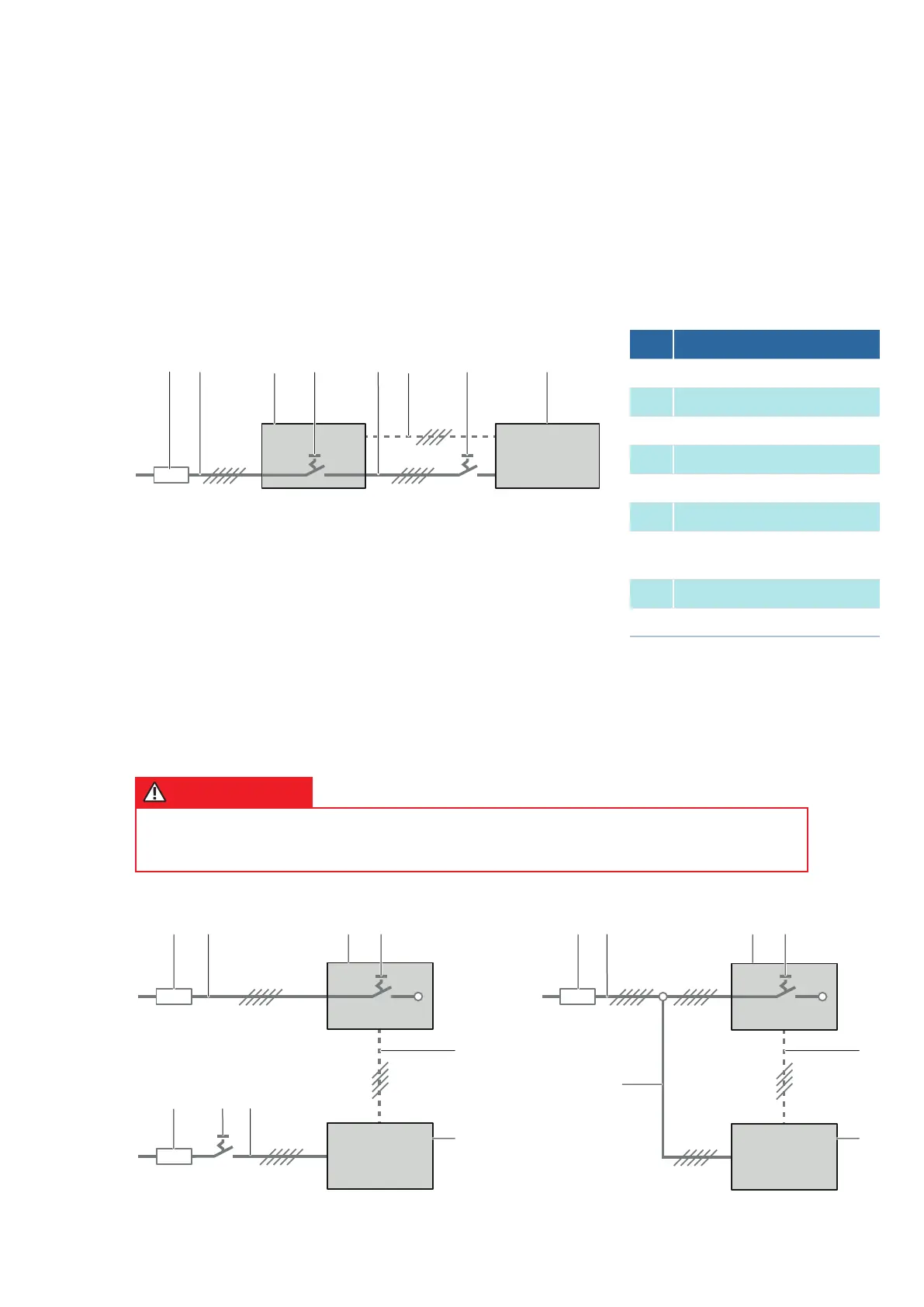
Avoid errors when wiring the EC Tower
The diagrams below show typical wiring errors when connecting the EC Tower.
EC Tower
OU
EC Tower
OU
2 2
7 5
6 6
8 8
4 43 3
9
5
1 1
Example of
INCORRECT
installation!
Example of
INCORRECT
installation!
EC Tower OU
7.8.1 Circuit diagram
7.8.2 Electrical wiring diagram
The circuit diagram varies depending on the unit size and version. The correct circuit diagram is enclosed with
the unit on delivery.
4 7521 6 83
The diagram below shows the standard wiring diagram of an EC Tower with one outdoor unit.
DANGER
Danger of death and of serious material damages due to wiring errors!
• Avoid the following typical wiring errors.
No. Description
1 Fuse (provided on-site)
2 Electrical supply to EC Tower
3 EC Tower
4 Master switch in EC Tower
5 Electrical supply to outdoor unit
6 Signal line
7
Repair switch for outdoor unit
(provided on-site)
8 Outdoor unit
9 Fuse (provided on-site)