148 EN/01.2019/G22 © STULZ GmbH – all rights reserved
ec tower technical manual
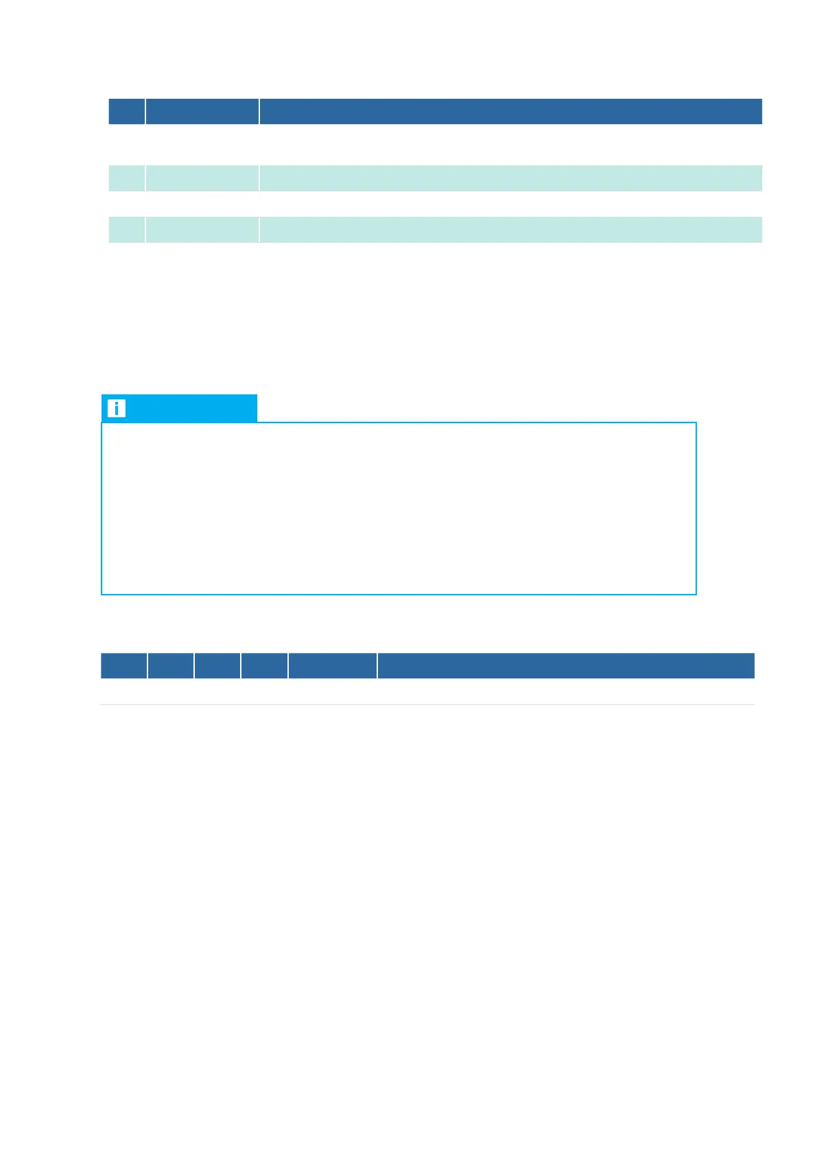
No. Designation Description
15
X5LED+,
X5LED-
Terminal for external LED for emitting a signal
16
X3S, X3-(-RV) Analog input, 010V DC signal at terminal S, GND at terminal -RV
17
X1X, X1Y X/Y remote control bus terminal, also the electrical supply
18
LED11 to LED13 Status display for digital outputs X4a-K1, X4b-K2 and X4c-K3
3.3 DIP switch S1
DIP switch S1 is used to select the program, set control damping and display behavior. Control damping is not
active in the EC Tower.
NOTE
become effective after the system has been rebooted. An exception to this are DIP switches
S27 and S28, which govern the behavior of the 7-segment display. These DIP switches for
display behavior can also be actuated during ongoing operation.
position of the InterfaceIIIk! The ON switch setting is the position that is closest to the center
of the board.
OFF.
DIP switches S11 to S14 are used for setting Program 8 of the EC Tower at the factory.
S11 S12 S13 S14 Program Designation
OFF OFF OFF ON 8 Direct frequency request
1 second, see “7. Starting up the InterfaceIIIk“ on page 157.
3.4 DIP switch S2
DIP switches S21 to S26 configure program-specific functions. DIP switches S27 and S28 configure
the behavior of the 7-segment display. You can find the precise DIP switch configurations in the section deal-
ing with each program.