24 EN/01.2019/G22 © STULZ GmbH – all rights reserved
EC TOWER TECHNICAL MANUAL
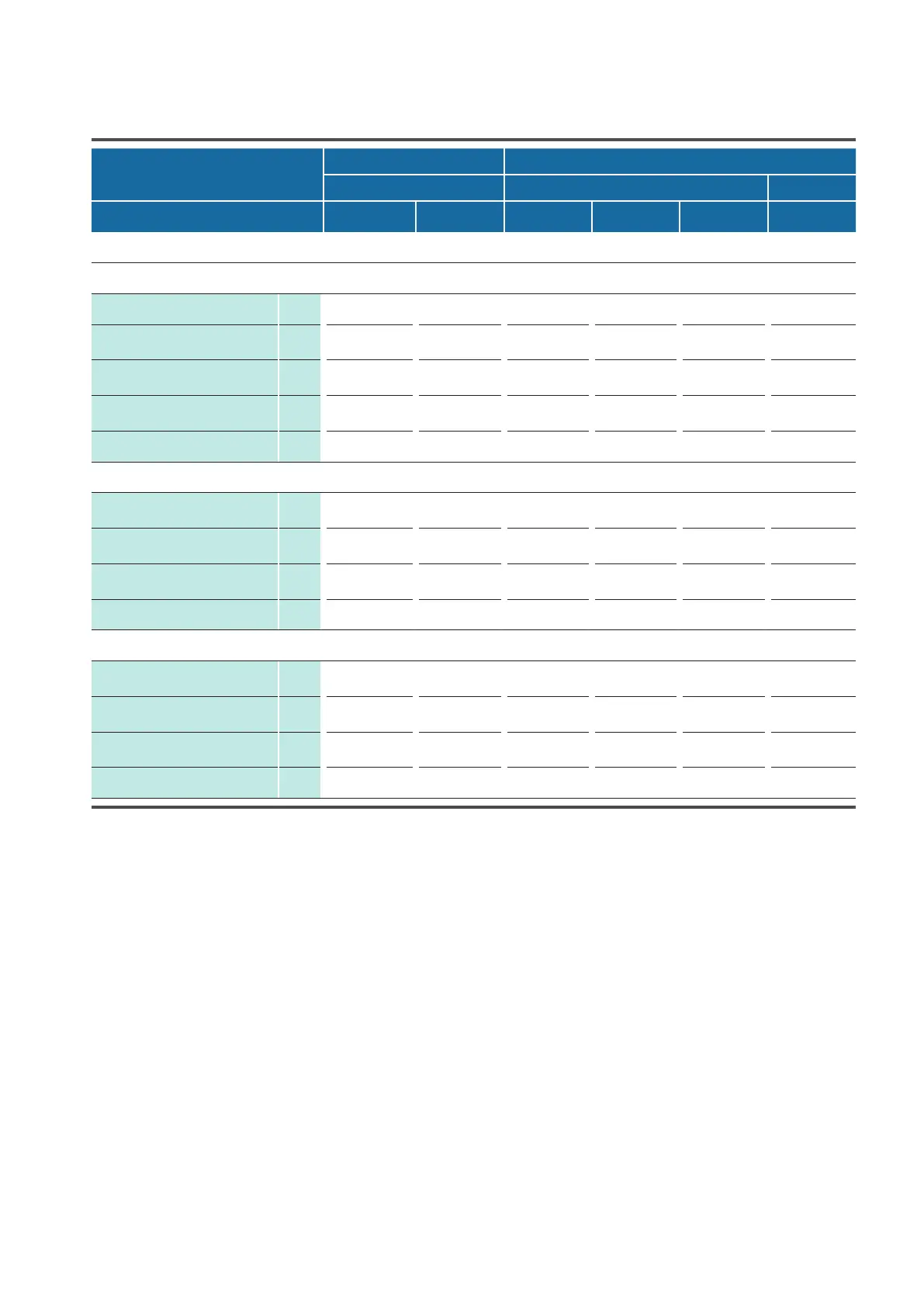
EC Tower model ECD/U
Size 1 Size 2
91 181 251
Outdoor unit
SRC 50 ZSS/
ZSXS
FDC 71 VNX FDC 140 VSA FDC 140 VSX FDC 200 VSA FDC 250 VSA
Design data
Design values at +24 °C/50 % RH indoors and +35 °C outdoors
Min. cooling capacity kW 2.3 2.8 5.0 5.0 7.0 10.0
Overall nominal cooling capa-
city (+24 °C/50 %), generated
kW 5.1 7.7 11.1 13.1 21.1 24.2
Total nominal cooling capacity
(+24 °C/50 %), available
kW 4.7 7.2 9.8 11.8 19.5 23.1
Sensible nominal cooling capa-
city (+24 °C/50 %), available
kW 4.5 6.8 9.3 10.8 17.6 21.4
Sensible heat ratio (SHR) * 0.96 0.94 0.95 0.92 0.9 0.93
Design values at +35 °C/30 % RH indoors and +35 °C outdoors
Overall nominal cooling capa-
city (+35 °C/30 %), generated
kW 6.6 10.7 14.0 16.9 22.0 27.1
Total nominal cooling capacity
(+35 °C/30 %), available
kW 6.3 10.2 12.7 15.6 20.4 25.8
Sensible nominal cooling capa-
city (+35 °C/30 %), available
kW 6.1 9.9 12.1 14.6 20.4 25.7
Sensible heat ratio (SHR) * 0.97 0.97 0.96 0.93 1.00 0.99
Design values at +18 °C/60 % RH indoors and +35 °C outdoors
Overall nominal cooling capa-
city (+18 °C/60 %), generated
kW 4.5 8.0 9.1 11.1 20.6 21.7
Total nominal cooling capacity
(+18 °C/60 %), available
kW 4.2 7.5 7.7 9.8 18.9 20.3
Sensible nominal cooling capa-
city (+18 °C/60 %), available
kW 3.9 6.2 7.4 8.9 15.4 17.2
Sensible heat ratio (SHR) * 0.93 0.82 0.96 0.91 0.82 0.85
6.2 EC Tower Technical Data
* The sensible heat ratio (SHR) is the quotient of sensible to total cooling capacity. The sensible heat ratio denotes the proportion in
percentage of cooling capacity that contributes to a lowering of the temperature. The remainder contributes to (unwanted) dehumidifica-
tion of the air.
For use in equipment rooms, the SHR should be higher than 0.9 at +24 °C and 50 %.