38
520 mm
121 mm
43 mm
205 mm
219 mm
A
EN/01.2019/G22 © STULZ GmbH – all rights reserved
EC TOWER TECHNICAL MANUAL
Indoor unit 091
Outdoor unit SRC 50 ZSS/ZSXS FDC 71 VNX
Connection of suction line inches 7/8" UNF*
Connection of injection line inches 5/8" UNF*
Indoor unit 091
Outdoor unit SRC 50 ZSS/ZSXS FDC 71 VNX
Suction line mm/inches 12/1/2" 16/5/8"
Injection line mm/inches 6/1/4" 10/3/8"
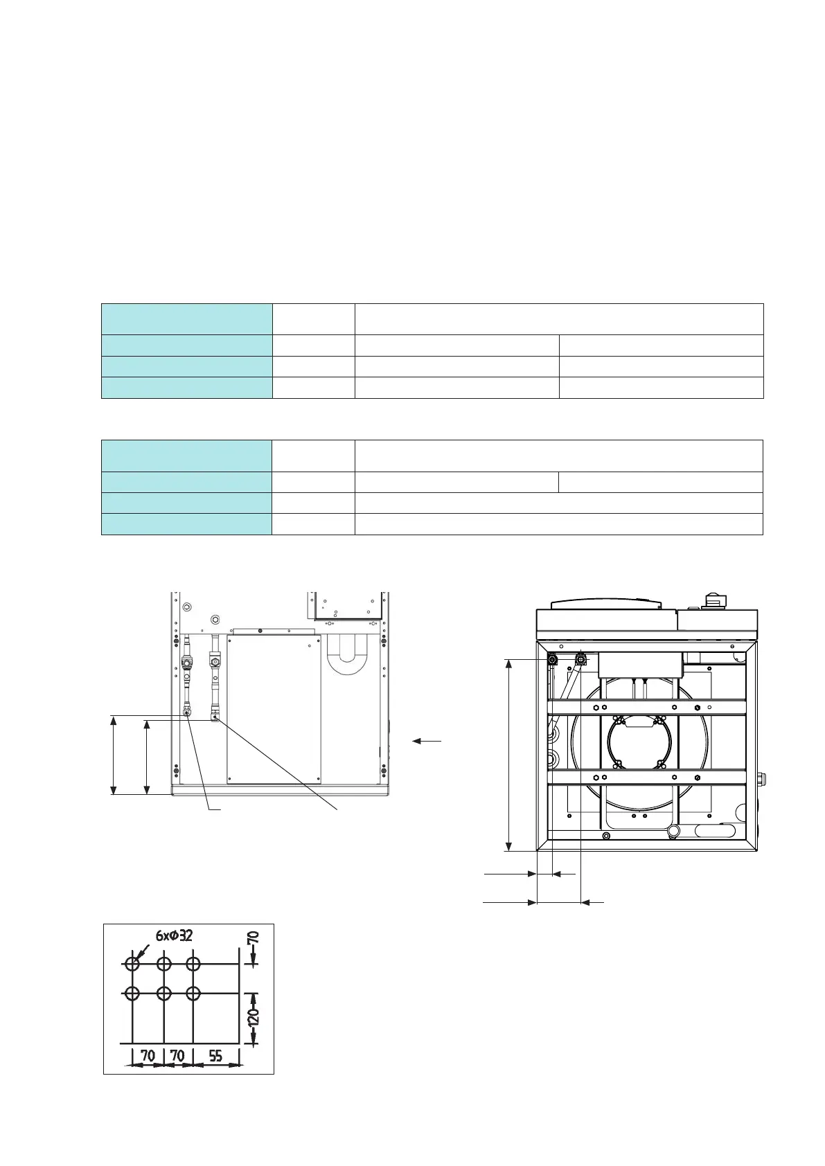
Downflow ECD 91
In Downflow units, the refrigerant pipes are routed out of the unit via the raised floor or through the holes in
the right-hand side panel. The holes have the dimensions stated below. The point of reference is the rear right
corner at the bottom.
7.3 Connecting the pipes
7.3.1 Location of refrigerant connections
Diameter of refrigerant pipes
Diameter of connections
* Flared joint.
View from below:
View A:
View from front:
All dimensions in mm.
Suction lineInjection line
The locations of the pipe connections have a tolerance of
± 10 mm.
The locations of the pipe connections have a tolerance
of ± 10 mm.