157 © STULZ GmbH – all rights reserved EN/01.2019/G22
ec tower technical manual
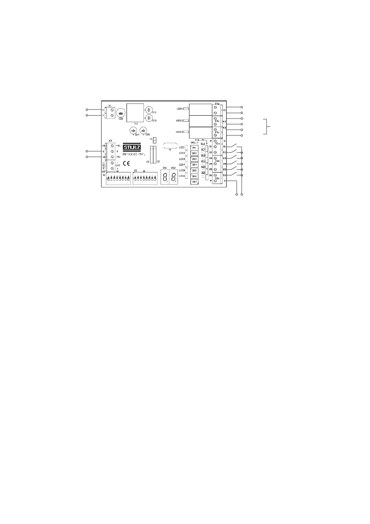
6.7 Connection diagram for Program 8
Procedure
1. Connect the Interface
IIIk as shown in the connection diagram below.
Digital outputs X4
Digital inputs X2
X4a-K1 alarm signal
+0...10 V DC
Analog input
Frequency setpoint
Ground
X/Y remote
controller bus
D1 remote ON/OFF
D2 cooling/heating mode
D3 center/remote center
D4 evaluate analog input
24-230 V AC/
X4b-K2
see table
"Digital outputs in program 8"
X4c-K3
1222310
7. Starting up the InterfaceIIIk
7.1 Initialization
The initialization phase commences when the InterfaceIIIk is connected to the X/Y remote control bus.
During this initialization phase, only the 7-segment display is active. None of the digital outputs or inputs are
active. The InterfaceIIIk ignores changes to the input signals during the initialization phase.
7.2 Initialization sequence
1. Both dots on the 7-segment display light up for 3 seconds.
2. The individual segments of the 7-segment display flash in a synchronous cycle as a display self-test.
3. The software version number, e.g. “3.9”, is shown for approximately 1 second.
4. A countdown ticks down.
- If the InterfaceIIIk is configured as a slave, the countdown runs from 3 to 0: duration approx. 1 second.
- If the InterfaceIIIk is configured as master, the countdown runs from 15 to 0: duration up to 3 minutes.
5. After the countdown, the number of the selected program is shown for approx. 1 second, e.g. “08” for Pro-
gram 8.
6. Next, the parameters set via DIP switches S27 and S28 are shown.