27 © STULZ GmbH – all rights reserved EN/01.2019/G22
EC TOWER TECHNICAL MANUAL
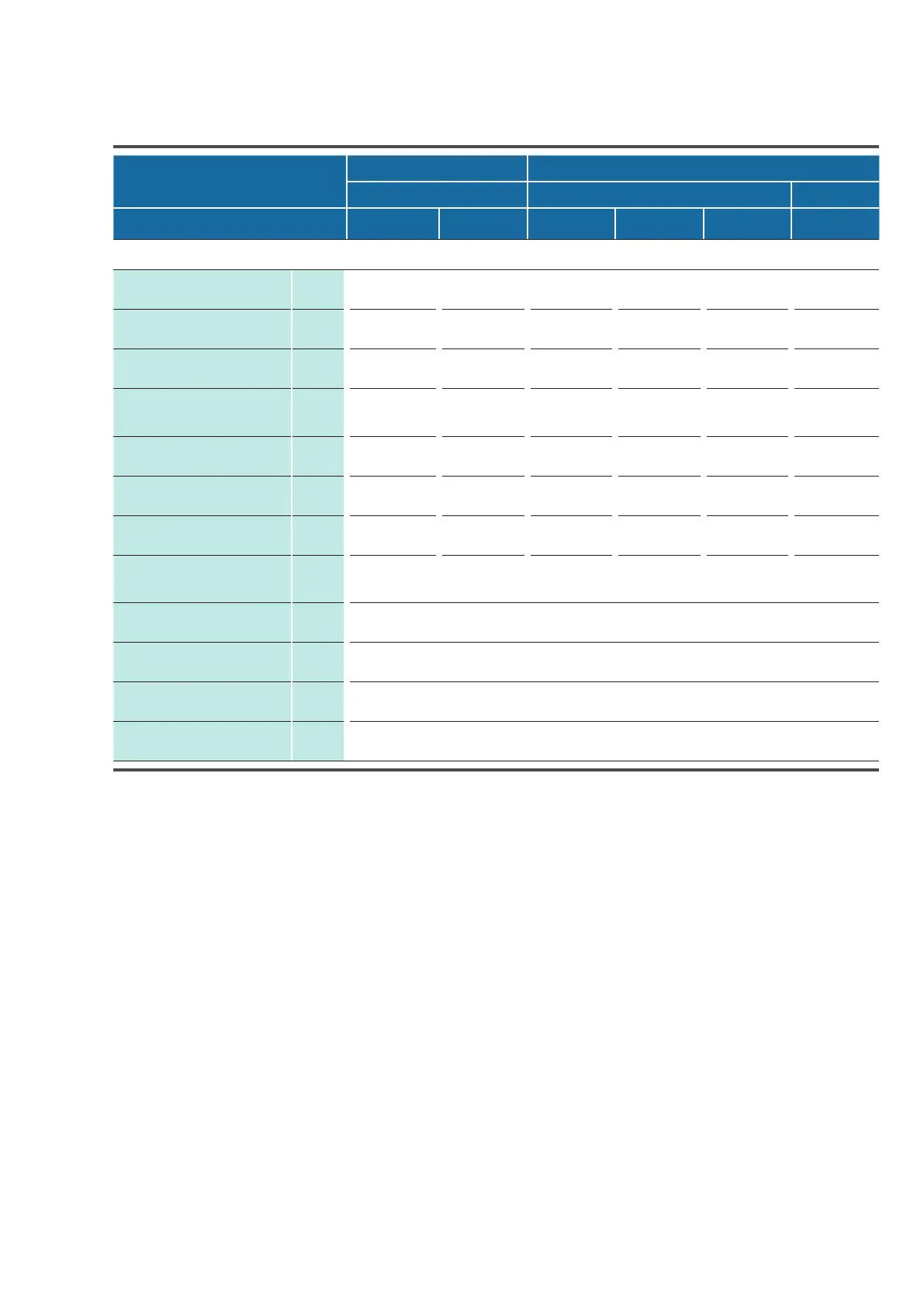
EC Tower model ECD/U
Size 1 Size 2
91 181 251
Outdoor unit
SRC 50 ZSS/
ZSXS
FDC 71 VNX FDC 140 VSA FDC 140 VSX FDC 200 VSA FDC 250 VSA
Electrical Data
External electrical supply
(to indoor unit)
V/Hz/
Ph
400/50/3,
N, PE
400/50/3,
N, PE
400/50/3,
N, PE
400/50/3,
N, PE
400/50/3,
N, PE
400/50/3,
N, PE
Voltage to outdoor units
(from indoor unit)
V/Hz/
Ph
230/50/1,
N, PE
230/50/1,
N, PE
400/50/3,
N, PE
400/50/3,
N, PE
400/50/3,
N, PE
400/50/3,
N, PE
Slow-blowing fuse A 25 25 50 50 50 63
Outdoor unit nominal opera-
ting current/start-up current/
fuse
A 6.1/5/16 10.5/5/16 6.9/5/16 7.0/5/16 11.3/5/16 13.4/5/ 20
Max. operating current of fan
(Version 07)
A 1.15 1.15 4.0 4.0 4.0 4.0
Operating current of elec.
heating coil
A 2 2.9 2 2.9 2 8.7 2 8.7 2 8.7 2 8.7
Max. operating current of
humidifier
A 3.2 3.2 5.4 5.4 5.4 8.7
Max. operating current (with
humidifier and elec. heating
coil)
A 19.25 20.65 33.6 33.7 43.4 43.4
Operating current of conden-
sate pump
A 0.7
Operating current of socket A 3.3
Power supply in indoor unit
Cable betw. outdoor/indoor
unit, min.
mm² 4 1.5 and 3 1.5 4 1.5 and 5 2.5
4 1.5 and
5 2.5
6.3 Electrical data and circuit diagram of EC Tower
Pay attention to the EC Tower operating and connection data („6.5 Operating and connection data of EC Tower“ on page 29).
The circuit diagram varies depending on the unit size and version. The correct circuit diagram is enclosed with the unit on delivery.