59 © STULZ GmbH – all rights reserved EN/01.2019/G22
EC TOWER TECHNICAL MANUAL
Procedure
1. Make sure that the master switch is off and the unit is not carrying voltage.
2. Open the door of the junction box using the supplied triangular socket
wrench.
3. Check that all circuit-breakers and control fuses in the electrical part are
switched off.
4. Tighten all screws in junction boxes 1 and 2.
5. Check that the contactor moves easily.
8. Starting up the EC Tower
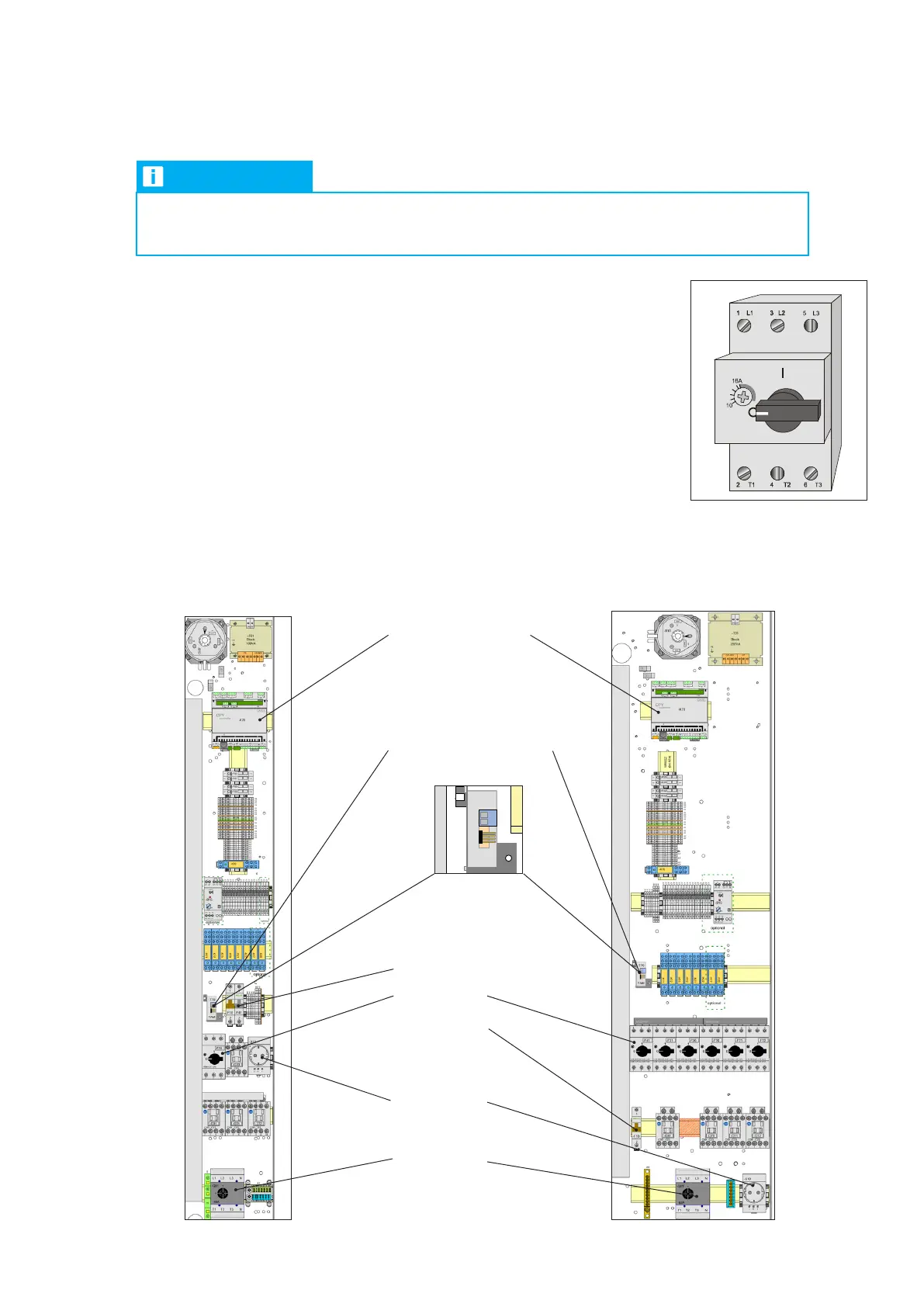
Circuit-breaker off
Junction box 1:
Size 1 - ECD/U 91
Junction box 1:
Size 2 - ECD/U 181/251
Control fuse
Circuit-breaker
Control fuses
External current transformer
(TAM) for steam humidifier
CPY controller for
steam humidifier
Socket 230V
Master switch
ufbauplan
Panel
Panneau
E
D
C
B
F
8765
4
3
2
1
8765
4
3
2
1
von
Blatt
Erstelldatum:
Gezeichnet:Entstanden aus:
Norm
Geprüft
Bearbeiter
Datum
Name
Datum
uftrags-Nr.:
Ident-Nr.:
Kunde:
F
Für dieses Dokument und den darin dargestellten Gegen-
stand behalten wir uns alle Rechte vor. Vervielfältigung,
Bekanntgabe an Dritte oder Verwertung seines Inhaltes
sind ohne unsere ausdrückliche Zustimmung verboten.
uftrags-Nr.
Hersteller:
05.91.13.0108/01 EC Tower 91 U
23.10.13
Klußmann
Jobst
0591130108_01
24
=MOD1
0010121 Tie./Schm. 18.09.13 27
Hutschiene mit Schrauben M5x25 befestigt.
1
2
3
-B05
TAM
-T70
1
2
0V24V
0V
100VA
Block
-T01
220-460V
PE
M24953
100mm
3
3
-X10
L
PE N
0
1
-F20
2
46
1
35
140M-C2E-C20
A2
A1
2
46
1
35
14
13
-Q31
C09 - C23
A2
A1
2
46
1
35
14
13
-Q71
C09 - C23
A2
A1
2
46
1
35
14
13
-Q72
C09 - C23
A2
A1
2
46
1
35
14
13
-Q70
C09 - C23
-K15
A2
A1
12
14
11
22
24
21
-K17
A2
A1
12
14
11
22
24
21
-K12
A2
A1
12
14
11
22
24
21
-K11
A2
A1
12
14
11
22
24
21
-K21
A2
A1
12
14
11
22
24
21
-K22
A2
A1
12
14
11
22
24
21
-K19
A2
A1
12
14
11
22
24
21
-K08
A2
A1
12
14
11
22
24
21
4
3
-F01
2
1
-F01
2
1
-F02
2
1
-F03
-K10
0
1
-F41
1
2
-F10
1
2
T1 T2 T3
N
L1
L2
-Q01
40A
L3 N
-X1
N1
PE1
N2
PE
-X2
14
-X2
PE1
-X2
A1
-X2
B1
-X2
C1
-X2
B1/GND
-X2
B1
-X2
B1
-X2
B1
-X2
A1
-X2
A1
-X2
A1
-X2
E1
-X2
E1
-X2
4
-X2
B
H8
3644
G
Fuse 5x20
TATA
Rel 1
G
23
24
21
-K70
8
0
20
2
0
0
1
4
0
1
2
3
-B10
optional
optional
Mit Klettband in der
E-Kastentür
befestigen.
Location of components in junction box 1
The diagrams below show the location of the components in junction box 1.
NOTICE
Before starting up for the first time, make sure the unit is installed and connected as described
in the “Installing the EC Tower” section.