60 EN/01.2019/G22 © STULZ GmbH – all rights reserved
EC TOWER TECHNICAL MANUAL
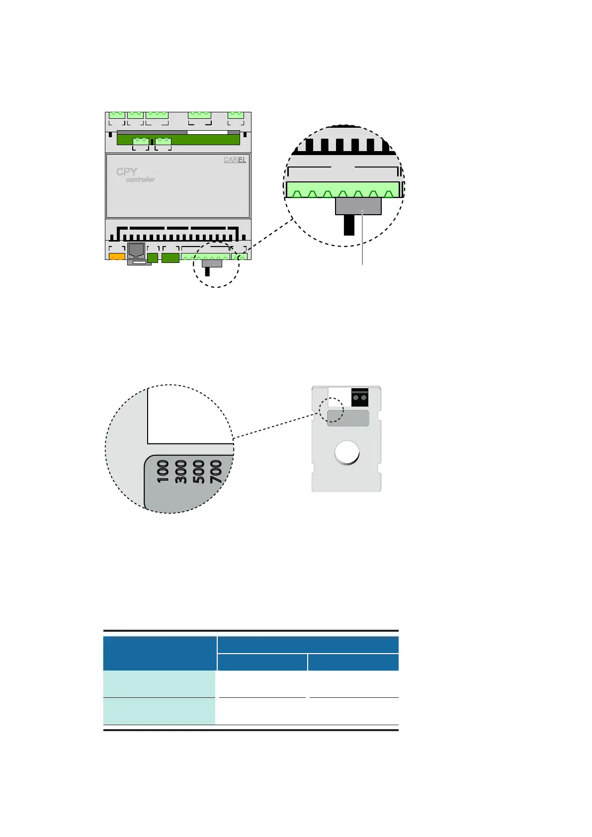
Diagram: Switch on terminals M24, M25, M26
6. On the CPY Controller, set the switch at terminals M24, M25 and M26 to the left (M24 / ON/OFF).
- The switch is installed on terminals M24, M25 and M26 on the CPY controller.
7. Insert the jumper on the external current transformer (TAM) in slot 100.
- The external current transformer (TAM) is situated in junction box 1 (see diagrams on page 59).
Diagram: External current transformer (TAM) with slot 100
8. Determine the pre-installed steam humidifier using the table below:
EC Tower
OEM model/steam output [kg/h]
KUET 1 / 1.5/3 KUET 2 / 5/8
Size 1
(ECD/U 91)
●
Size 2
(ECD/U 181 and 251)
●
Table: Sizes and steam output of the EC Tower
700
500
300
100
CPY
c
o
nt
r
o
ller
CAREL
M8 M5M2M1
M12
J1
M6 M10
M11
M7
M9M3
M14
2
2
1
2
1
2
1
2
3
1
2
3
2
1
1
1
2
3
1
2
3 4 5 6 7
2
3
1
2
JS6
1
HCT
1
2
M2M1
M12
1
2
3
1
2
3 4 5 6 7
HCT
1
2
Switch M24 / ON/OFF