56 EN/01.2019/G22 © STULZ GmbH – all rights reserved
EC TOWER TECHNICAL MANUAL
Procedure
1. Make sure that the outdoor unit receives its electrical supply via the indoor unit (see section “7.8.2 Electri-
cal wiring diagram“ on page 53).
2. Connect the electrical supply of the outdoor unit in junction box 1 as per the circuit diagram (see page 4 of
the relevant circuit diagram).
3. For size 1, connect the electrical supply of the outdoor unit to the control fuse (F41).
- Connect the N wire and PE conductor to terminals (X1/N4 and X1/PE4) in junction box 1 as per the
circuit diagram.
- For size 1, the electrical supply of the outdoor unit has 1 phase.
4. For size 2, connect the electrical supply of the outdoor unit to the circuit-breaker (F41).
- Connect the PE conductor to terminal (X0/PE2) and the N wire to terminal (X1/N1) in junction box 1
as per the circuit diagram.
- For size 2, the electrical supply of the outdoor unit has 3 phases.
Procedure
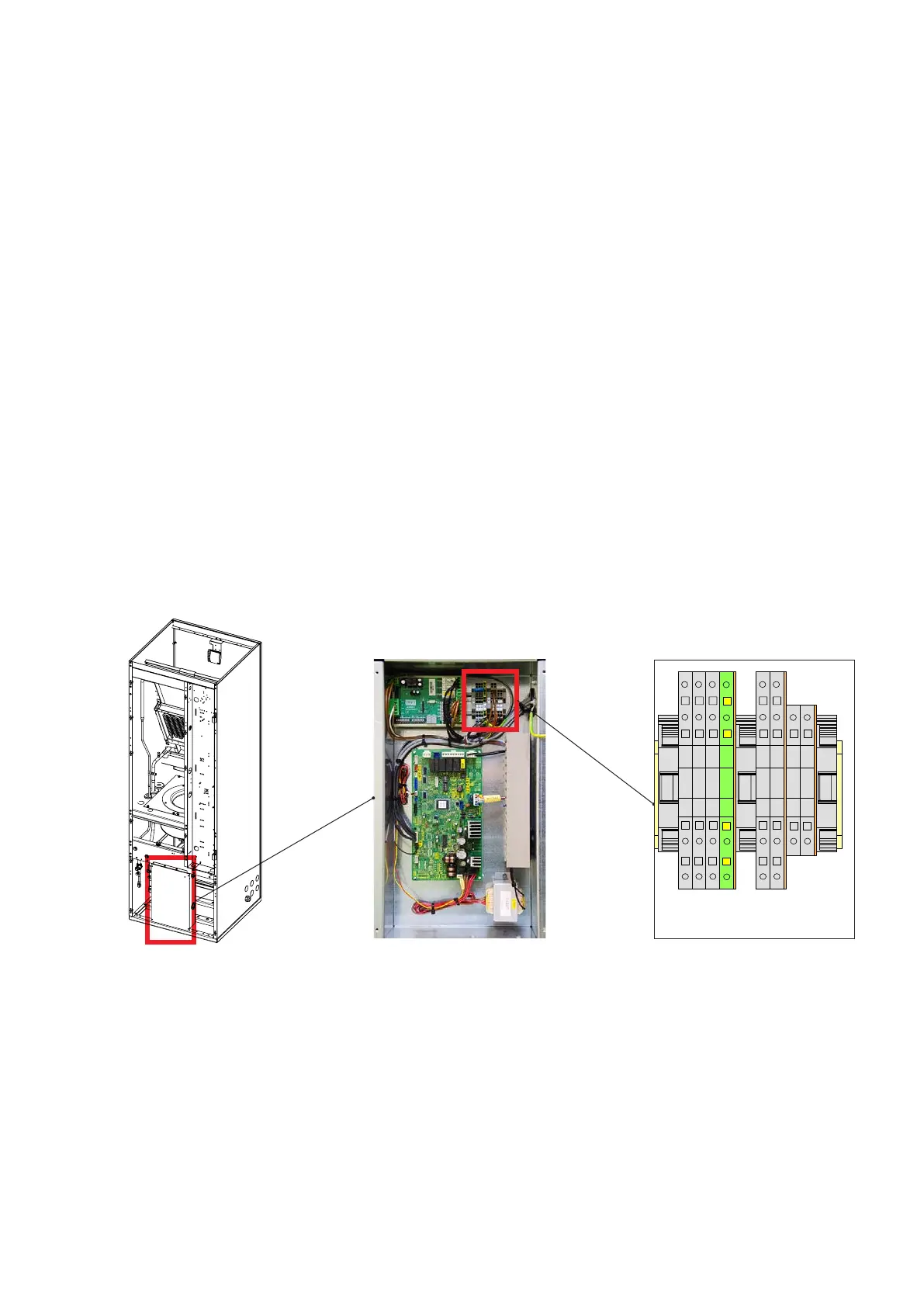
1. Connect the signal line of the outdoor unit to terminals (X1/1,2,3) in junction box 2 as per the circuit
diagram.
2. Connect the PE conductor to terminal (X1/PE) in junction box 2 as per the circuit diagram.
7.9.2 Connecting the outdoor unit signal lines in junction box 2
Junction box 2 Terminals X1
Aufbauplan
Panel
Panneau
E
D
C
B
F
A
E
D
C
B
A
876543
2
1
876543
1
von
Blatt
Erstelldatum:
Gezeichnet:Entstanden aus:Norm
Geprüft
Bearbeiter
Datum
NameDatum Änderung
Auftrags-N r.:
Ident-Nr.:
Kunde:
F
Für dieses Dokument und den darin dargestellten Gegen-
stand behalten wir uns alle Rechte vor. Vervielfältigung,
Bekanntgabe an Dritte oder Verwertung seines Inhaltes
sind ohne unsere ausdrückliche Zustimmung verboten.
Auftrags-Nr.
Her stel ler:
EC-Tower 251D
08.08.13
Tie./Schm.
Jobst
0591130105_01
27
=MOD1
Tie./Schm. 08.08.13
27
CNWO
CNW1
CNW2
CNN
CNH
CNB
CNI
-T41
RD RD
BN BN
BK BK
110 2030
180mm
M24387
75 x 37,5 x 205 (HxBxL)
-K40
-K41
D1
D2
D3
D4
D5
D6
K1
K1
K2
K2
K3
K3
+RV
S
-RV
-
+
N
N
X
Y
2
-X4
1
-X4
PE
-X1
3
-X1
2
-X1
1
-X1
3
-X4
4
-X4
PAGE 1 / 1
02.02.2017
EC TOWER 091 D (VERSION 6)
Pay attention to the electrical wiring diagram (see section “7.8.2 Electrical wiring diagram“ on page 53).