99 © STULZ GmbH – all rights reserved EN/01.2019/G22
ec tower technical manual
Procedure
1. Fit suitable sealing tape on the upper and lower
contact surfaces (3, 4) of the adapter panel (2).
2. -
ing unit (5).
3. For size 1: Bend the integrated tabs (1) slightly to
secure the adapter panel to the air conditioning
unit.
4. Install the servo motor (6) on the louver damper
(7) as described in the servo motor Installation
louver damper servo motor“ on page 200).
5. -
el(2). The servo motor is facing the right.
6. Fasten the louver damper (7) to the adapter
panel(2).
7. Guide the cable of the louver damper (7) servo
motor through the hole in the adapter panel (2).
13.8.1 Installing the louver damper
Size 1 Size 2
1 2
5
4
62
7
62
7
3
EC Tower
51-5670-16 ECTower_Vorlage.indd 1
03.08.16 16:31
EC Tower
51-5670-16 ECTower_Vorlage.indd 1
03.08.16 16:31
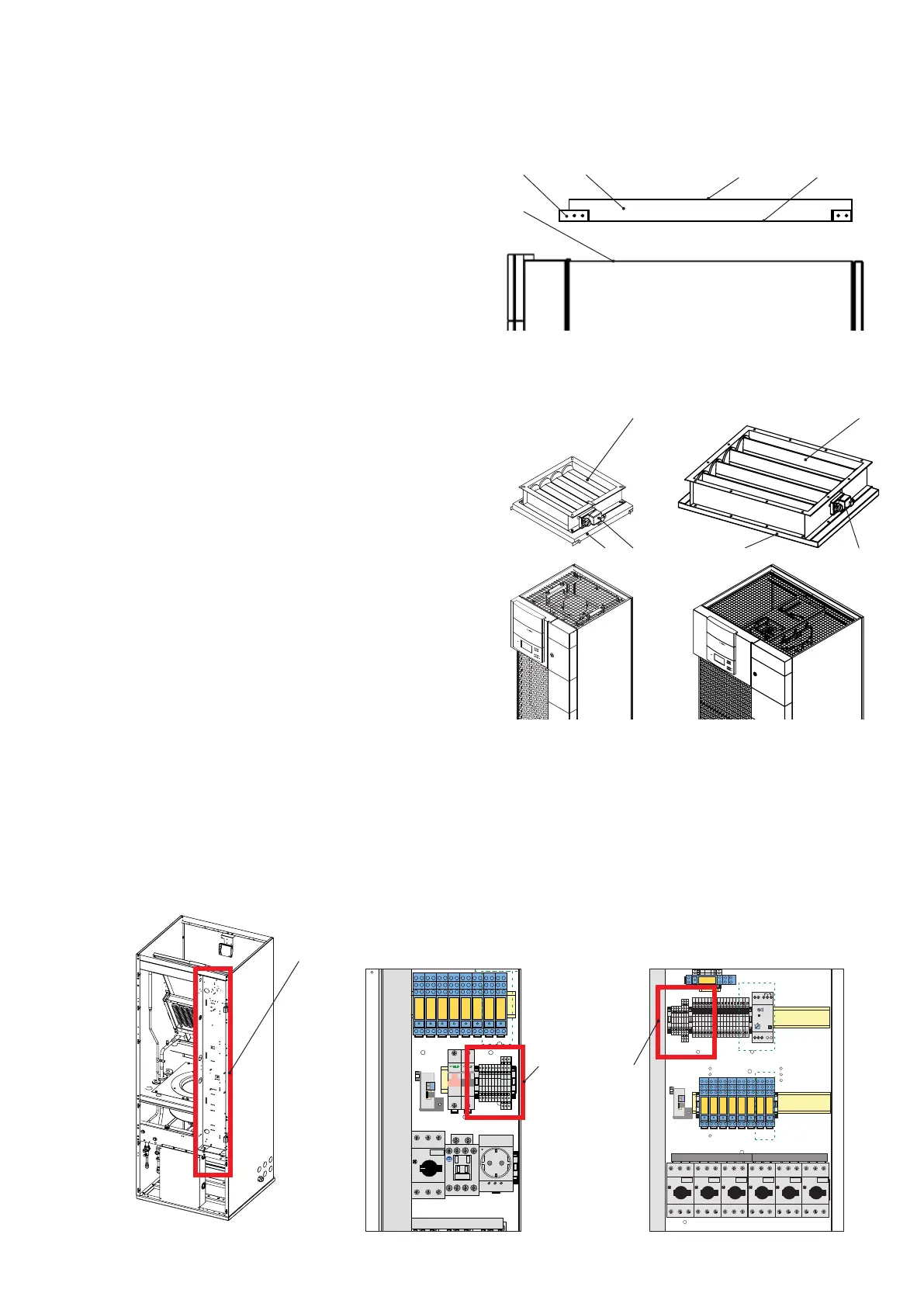
1. Connect the servo motor cable in junction box 1 to terminals (X4) as per the circuit diagram
- Position of terminal X4: see below.
13.8.2 Electrically connecting the louver damper
ufbauplan
Panel
Panneau
E
D
C
B
F
8765
4
3
2
1
8765
4
3
2
1
von
Blatt
Erstelldatum:
Gezeichnet:Entstanden aus:
Norm
Geprüft
Bearbeiter
Datum
Name
Datum
uftrags-Nr.:
Ident-Nr.:
Kunde:
F
Für dieses Dokument und den darin dargestellten Gegen-
stand behalten wir uns alle Rechte vor. Vervielfältigung,
Bekanntgabe an Dritte oder Verwertung seines Inhaltes
sind ohne unsere ausdrückliche Zustimmung verboten.
uftrags-Nr.
Hersteller:
05.91.13.0108/01 EC Tower 91 U
23.10.13
Klußmann
Jobst
0591130108_01
24
=MOD1
0010121 Tie./Schm. 18.09.13 27
Hutschiene mit Schrauben M5x25 befestigt.
1
2
3
-B05
TAM
-T70
1
2
0V24V
0V
100VA
Block
-T01
220-460V
PE
M24953
100mm
3
3
-X10
L
PE N
0
1
-F20
2
46
1
35
140M-C2E-C20
A2
A1
A2
A1
A2
A1
A2
A1
2
46
1
35
14
13
-Q70
C09 - C23
-K15
A2
A1
12
14
11
22
24
21
-K17
A2
A1
12
14
11
22
24
21
-K12
A2
A1
12
14
11
22
24
21
-K11
A2
A1
12
14
11
22
24
21
-K21
A2
A1
12
14
11
22
24
21
-K22
A2
A1
12
14
11
22
24
21
-K19
A2
A1
12
14
11
22
24
21
-K08
A2
A1
12
14
11
22
24
21
4
3
-F01
2
1
-F01
2
1
-F02
2
1
-F03
-K10
-F41
1
2
-F10
1
2
T1 T2 T3
N
L1
L2
-Q01
40A
L3 N
-X1
N1
PE1
N2
PE
1
-X4
-X4
-X4
4
-X4
-X4
-X4
-X4
-X4
-X4
1
-X4
-X2
14
-X2
PE1
-X2
A1
-X2
B1
-X2
C1
-X2
B1/GND
-X2
B1
-X2
B1
-X2
B1
-X2
A1
-X2
A1
-X2
A1
-X2
E1
-X2
E1
-X2
4
-X2
B
H8
3644
G
Fuse 5x20
TATA
Rel 1
G
23
24
21
-K70
8
0
20
2
0
0
1
4
0
1
2
3
-B10
optional
optional
Mit Klettband in der
E-Kastentür
befestigen.
$XIEDXSODQ
3DQHO
3DQQHDX
(
'
&
%
)
$
(
'
&
%
$
YRQ
%ODWW
(UVWHOOGDWXP
*H]HLFKQHW(QWVWDQGHQ DXV1RUP
*HSU¾IW
%HDUEHLWHU
'DWXP
1DPH'DWXP QGHUXQJ
$XIWUDJV1U
,GHQW1U
.XQGH
)
)¾U GLHVHV 'RNXPHQW XQG GHQ GDULQ GDUJHVWHOOWHQ *HJHQ
VWDQG EHKDOWHQ ZLU XQV DOOH 5HFKWH YRU 9HUYLHOI¦OWLJXQJ
%HNDQQWJDEH DQ 'ULWWH RGHU 9HUZHUWXQJ VHLQHV ,QKDOWHV
VLQG RKQH XQVHUH DXVGU¾FNOLFKH =XVWLPPXQJ YHUERWHQ
$XIWUDJV1U
+HUVWHOOHU
(& 7RZHU '
7LH6FKP
-REVW
B
02'
7LH6FKP
0,76 8%,6+ ,
7(03 212))
6
;
<
=
;
1
1=1$
1
1111
;
/ 3(
1
7 7 7
/
/ /
)
&(%ELV &(&
&(& ELV &(&
)
&(% ELV &(&
&(& ELV &(&
)
&(% ELV &(&
&(& ELV &(&
)
&(%ELV &(&
&(& ELV &(&
)
&(%ELV &(&
&(& ELV &(&
;$
$% $% $%$%
)
)
)
)
$
$
4
& &
$
$
4
& &
$
$
4
& &
$
$
4
& &
.
$
$
.
$
$
.
$
$
.
$
$
.
$
$
.
$
$
.
$
$
.
$
$
.
$
$
.:
0D[ 0LQ &RP
)XQNWLRQ
(6
%
a
%
% %
$
$
02(//(5
7 7 7
1
/ /
4
$
/ 1
)
;
;
;
;
;
;
;
;
;
;
;
;
;
;
;
;
;
;
;
;
;
;
;
;
;
;
;
;
;
;
;
;
;
;
;
;
;
;
;
(
;
(
;
%
;
%
;
%
;
$
;
$
;
$
;
3(=3(3(3(3(3(3(3(3(3(3(
;
$/$/*1' 956(7$%$%
+
*
)XVH [
7$7$
5HO
*2**1'21'5(9(9/6/6&6&6
21
7$ 5DWH
21
5HO
21
$
%
/
/5()
7/57/5
.
%
M26467 M26466
)
&(% ELV &(&
&(& ELV &(&
RSWLRQDO
RSWLRQDO
0LW .OHWWEDQG LQ GHU
(.DVWHQW¾U
EHIHVWLJHQ
Detail: Junction box 1
Size 1 - ECD/U 91
Junction
box 1
Detail: Junction box 1
Size 2 - ECD/U 181/251
Terminals X4