181 © STULZ GmbH – all rights reserved EN/01.2019/G22
ec tower technical manual
27
+040000030 rel. 1.0 - 11.02.2008
ENG
Power supply: 24 Vac, from -15 % to +10 %, 50/60 Hz (protect with a 1 A fast-blow fuse, installer’s
responsibility, to be connected in series with terminal M8.1)
Power input: 10 VA (not including utilities) – 105 VA max. (including utilities)
Inputs and outputs: see electrical connections
Operating condi-
tions:
0T60 °C; <90% rH non-condensing
Storage conditions: -10T70 °C; <90% rH non-condensing
Environmental
pollution:
class 2
External TAM code 09C412A017 / 09C565A042
Software class class A
Type of action 1.C - 1.Y
Assembly DIN rail
Class according to
protection against
electric shock
double insulation
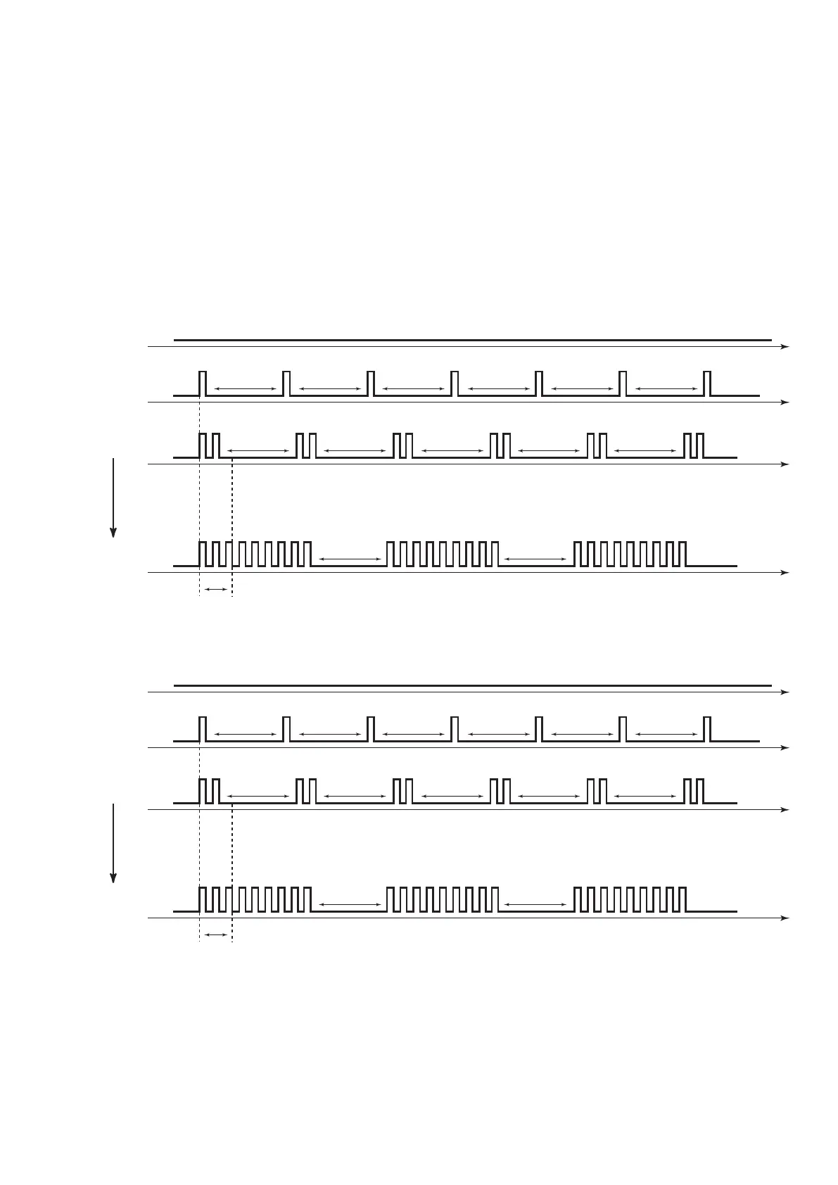
Alarm diagram (red LED) “short ashes”
ALARM
NO
ON
OFF
tim
ON
OFF
tim
1111111
3 s 3 s 3 s 3 s 3 s 3 s
1 ash
ON
OFF
tim
1 2 2222211111
3 s 3 s 3 s 3 s 3 s
2 ashes
ON
OFF
tim
15 9 15 9 15 9
3 s 3 s
9 ashes
1 s
Alarm diagram (red LED) “long ashes”
ALARM
NO
ON
OFF
tim
ON
OFF
tim
1111111
3 s 3 s 3 s 3 s 3 s 3 s
1 ash
ON
OFF
tim
1 2 2222211111
3 s 3 s 3 s 3 s 3 s
2 ashes
ON
OFF
tim
15 9 15 9 15 9
3 s 3 s
9 ashes
1 s
9. TECHNICAL SPECIFICATIONS
10. ALARMS
7.2.5 Understanding the red alarms LED