19 © STULZ GmbH – all rights reserved EN/01.2019/G22
EC TOWER TECHNICAL MANUAL
THIR1THIR2
Gas line
Heat exchanger
THIA
THIR3
Injection line
Detailed view: Interior of EC Tower
Sensors in the EC Tower
The detailed view from the interior of the EC Tower shows the names and locations of sensors used in the EC
Tower. The table describes the function of these sensors.
The steam humidifier starts up if the humidity setpoint, including start value, is exceeded. The C7000AT and CPY
controllers regulate the steam production of the steam humidifier. It is controlled proportionally via a 010 V signal.
The steam humidifier is described in the following section:
• Section “14.2 Steam humidifier OEM User Manual“ on page 164.
Setting the steam humidifier on the C7000AT is described in the following manual:
• User Manual “C7000 Controller for EC Tower”.
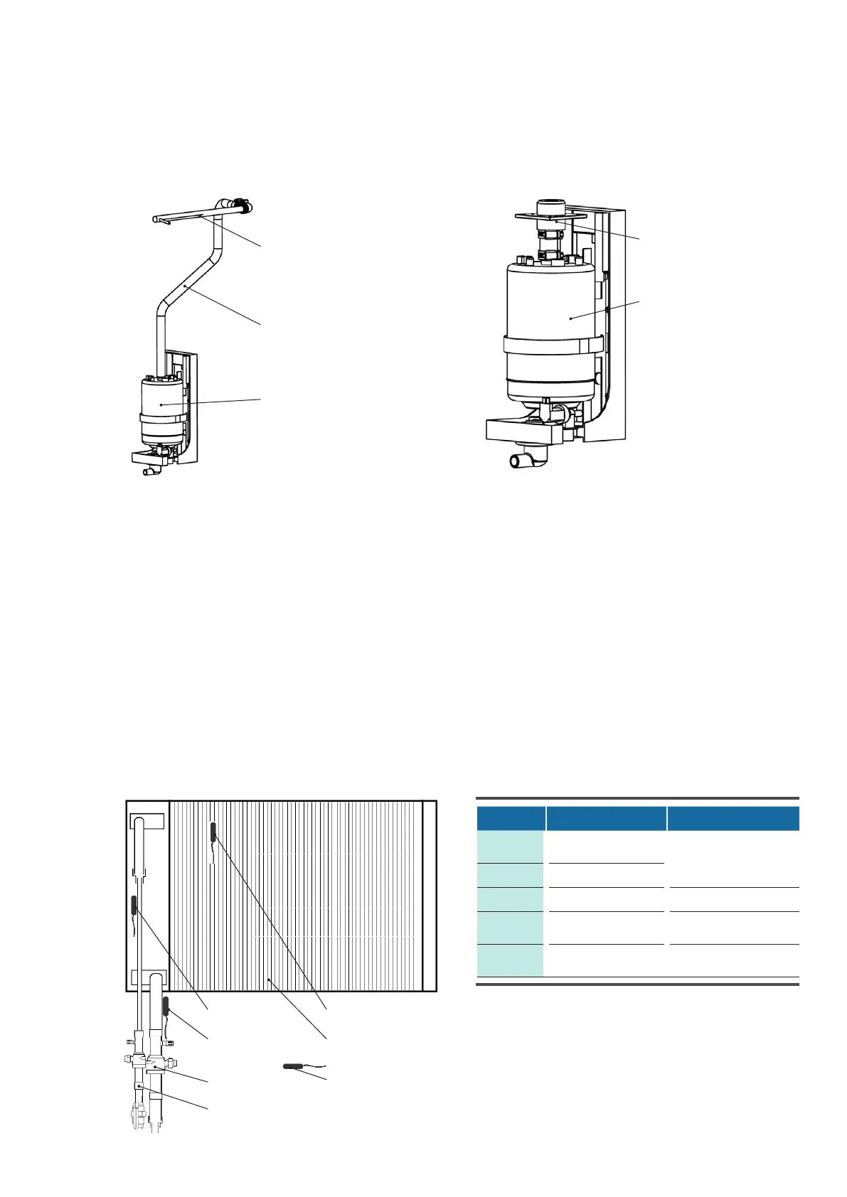
Steam cylinder
Hose
Steam lance
Steam cylinder
Steam nozzle
Steam humidifier
The EC Tower is factory-fitted with a steam humidifier. The diagrams below show the components of the
steam humidifier in the Upflow and Downflow units.
Steam humidifier in Upflow units Steam humidifier in Downflow units
Sensor Location Function
THIR1
Surface of heat
exchanger
Overheating and frost
protection
THIR2 Injection line
THIR3 Gas line Overheating protection
THIA Interior of EC Tower
No switching or techni-
cal function
B01
Return air duct of EC
Tower
Temperature/humidity
sensor