40
Sx
Ex
Sz
Ez
55 70 70
120 70
2 x 50
4 x 32
x
z
y
Ey
Sy
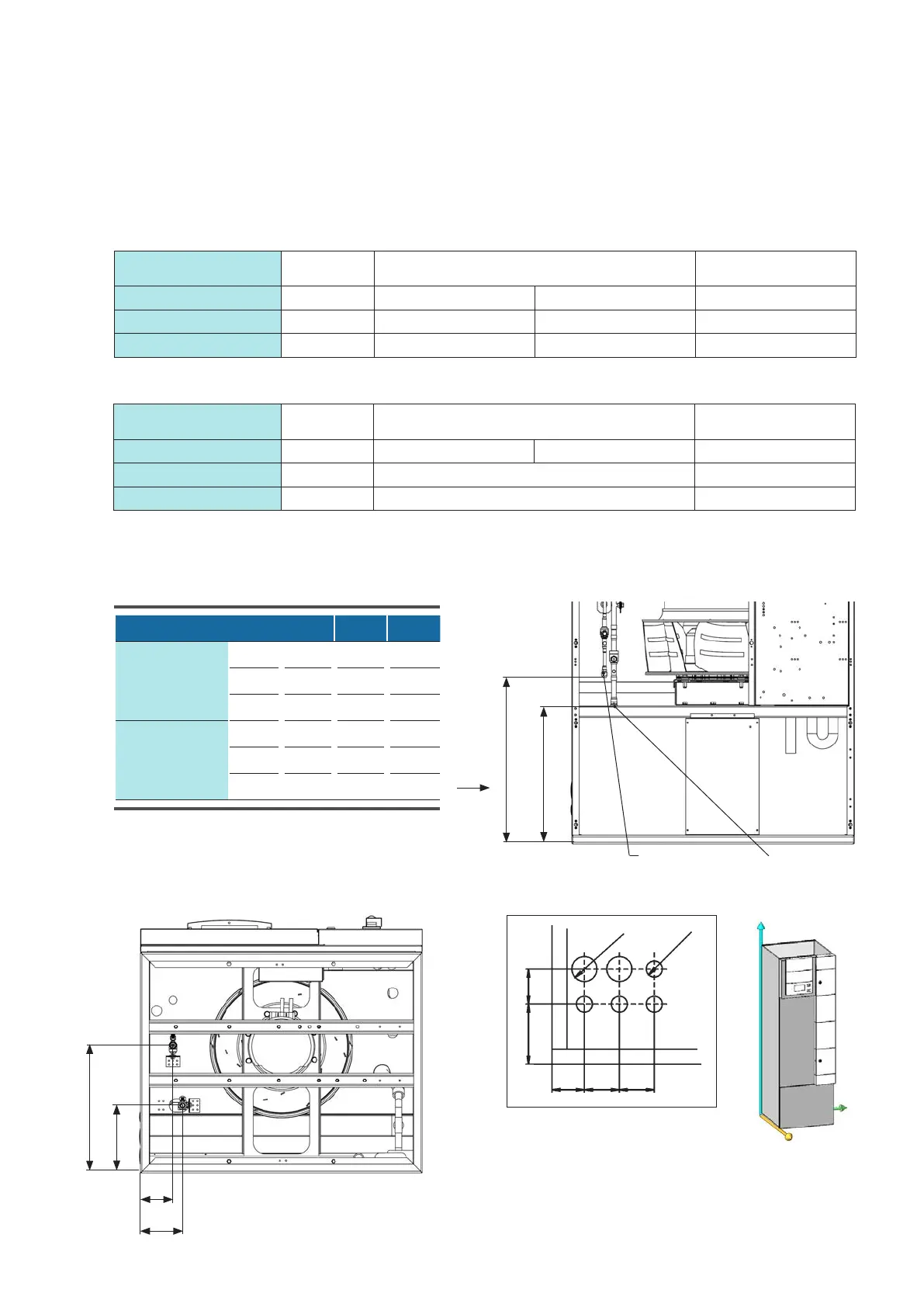
A
Indoor unit 181 251
Suction line
mm Sx 127 145
mm Sy 365 375
mm Sz 236 237
Injection line
mm Ex 115 116
mm Ey 589 622
mm Ez 450 436
EN/01.2019/G22 © STULZ GmbH – all rights reserved
EC TOWER TECHNICAL MANUAL
Indoor unit 181 251
Outdoor unit FDC 140 VSX/VSA FDC 200 VSA FDC 250 VSA
Connection of suction line inches 7/8" UNF** / 22 mm* 22 mm / 28 mm*
Connection of injection line inches 5/8" UNF** 3/4" UNF**
Indoor unit 181 251
Outdoor unit FDC 140 VSX/VSA FDC 200 VSA FDC 250 VSA
Suction line mm/inches 16/5/8" 22 / 7/8" / 25 or 28* 22 / 7/8" / 25 or 28*
Injection line mm/inches 10/3/8" 10/3/8" 12/1/2"
Downflow ECD 181/251
In Downflow units, the refrigerant pipes are routed out of the unit via the raised floor or through the holes in the
left-hand side panel. The holes have the dimensions stated below. The point of reference is the rear left corner
at the bottom.
Diameter of refrigerant pipes
Diameter of connections
* Solder lug. Diameter 25 or 28 mm if the length of the refrigerant pipe is at least 35 m.
** Flared joint.
Connection dimensions
View from below:
View from front:
The locations of the pipe connections have a toleran-
ce of ± 10 mm.
View A:
All dimensions in mm.
Injection line Suction line