10-4 SPARCclassic/SPARCclassic X/SPARCstation LX Service Manual • November 1993
10.4 Main Logic Board Layouts
The main logic board (MLB) resides in the bottom half of each system unit (see
FIGURE 10-4). FIGURE 10-1 shows a simplified layout of the SPARCclassic and the
SPARCclassic X terminal main logic board.
TABLE 10-2 lists acronyms and
abbreviations for certain components.
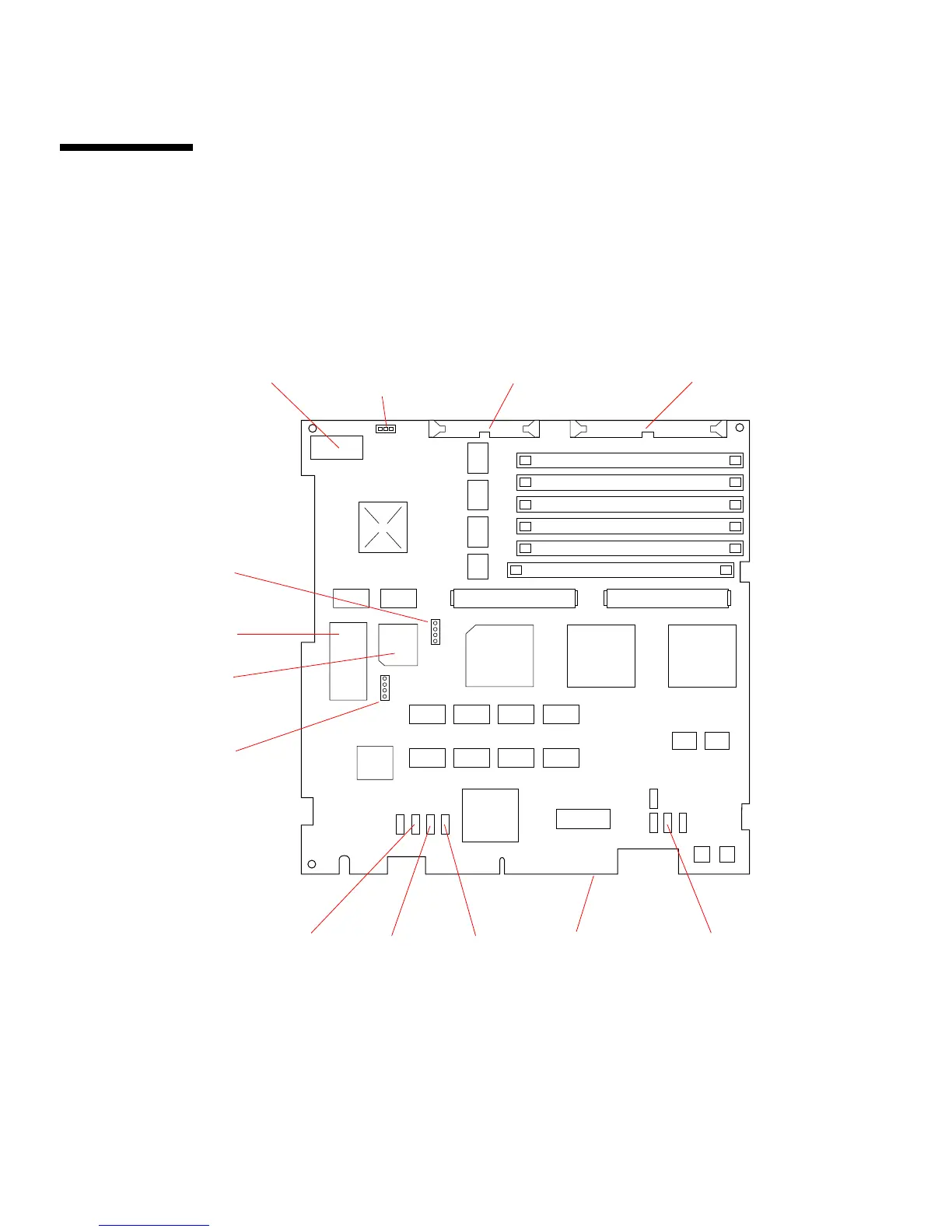
FIGURE 10-1 Main Logic Board Layout—SPARCclassic/SPARCclassic X Systems
FIGURE 10-2 and FIGURE 10-3 illustrate the SPARCstation LX main logic boards.
I/O board
Hard drive
data connector
LED/speaker
AUI PTC SCSI terminator
PTC
Keyboard/Audio power
PTC
Keyboard soft
power-on
connector
Diskette drive
data connector
Power supply
connector
SIMM slot U0304
SIMM slot U0301
SIMM slot U0402
SIMM slot U0303
SIMM slot U0302
SIMM slot U0401
Bank 1
Bank 2
Bank 3
Bank 1
Bank 2
Bank 3
SBus slot 0 SBus slot 1
NVRAM
Boot PROM
nitor control connector
(used by SBus
frame buffer cards)
mouse PTC
edge connector
connector