1-4 SPARCclassic/SPARCclassic X/SPARCstation LX Service Manual • November 1993
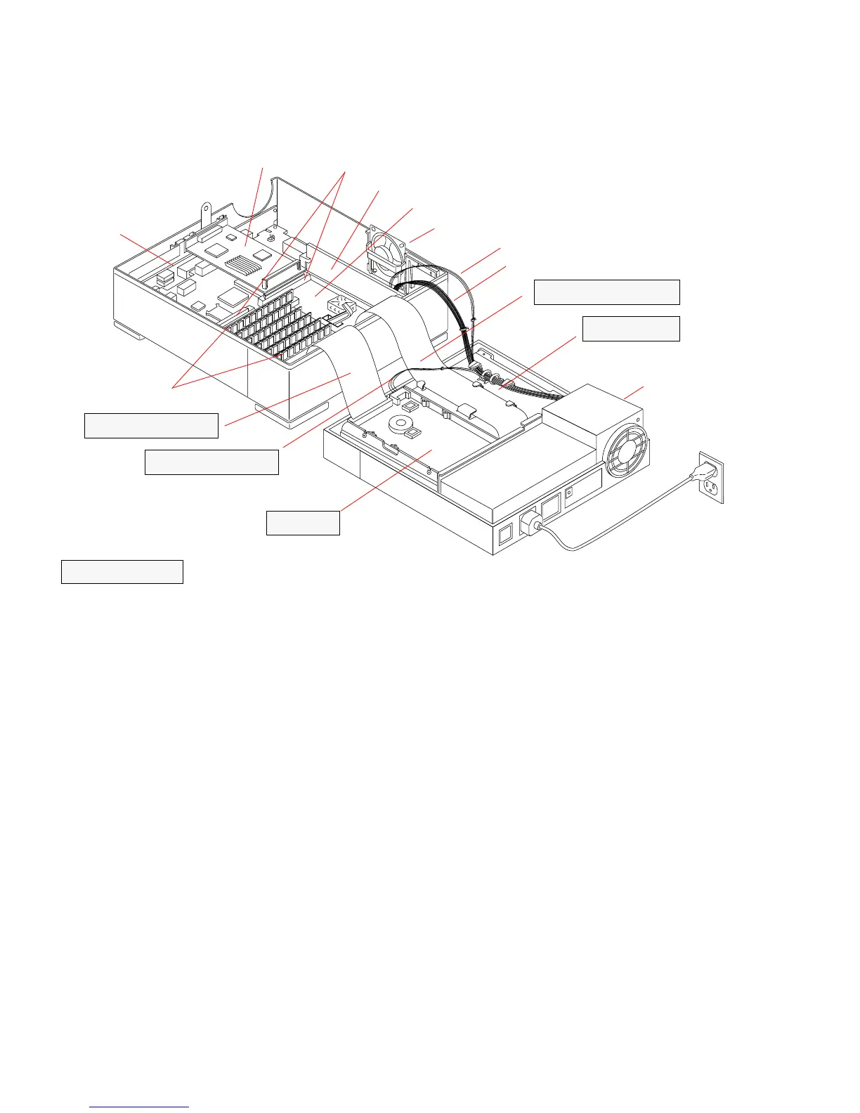
FIGURE 1-3 System Unit Internal Components
1.1.1 Main Logic Board
The main logic board (MLB) resides in the bottom half of the system unit. It plugs
into the system input/output (I/O) board, which provides all of the external
connectors to the system unit’s back panel (see
FIGURE 1-2).
The different SPARCclassic/SPARCclassic X/SPARCstation LX MLB layouts are in
Chapter 10 “System Board Overview.
FIGURE 10-1 shows a simplified layout of the
SPARCclassic and the SPARCclassic X main logic board, while
FIGURE 10-2 and
FIGURE 10-3 show the SPARCstation LX main logic boards.
Customer replaceable units (CRUs) residing on the main logic board include:
■ Memory modules
■ Video single in-line memory modules (VSIMMs) (SPARCstation LX only)
■ SBus cards
■ Nonvolatile random access memory (NVRAM)
UNIT BOTTOM
Main logic board
SBus slots
SBus card
Speaker/Power LED assembly
Main logic power cable
Power supply
DSIMMs
Hard drive data cable
UNIT TOP
VSIMM module (option on SPARCstation LX only)
System
(system option)
(fully populated)
I/O board
Keyboard soft power-on cable
Hard drive
Hard drive power cable
Diskette drive data cable
Diskette drive
Not applicable to the=
SPARCclassic X terminal