Chapter 10 System Board Overview 10-7
Visually identify each CRU by looking at the appropriate system board layout
illustration from
FIGURE 10-1, FIGURE 10-2,orFIGURE 10-3, and by looking at the unit
bottom illustration in
FIGURE 10-4. TABLE 10-2 lists acronyms and abbreviations for
certain components of the MLB.
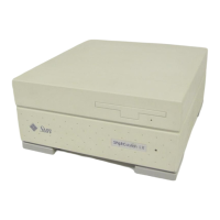
The SPARCclassic/SPARCclassic X/SPARCstation LX system board CRUs are listed
below.
Unit bottom
■ DSIMMs
■ VSIMM
■ SBus cards
■ Speaker/power LED assembly
■ Main logic board
■ NVRAM
■ System I/O board
Internal cables
■ Diskette drive data cable (Not applicable to SPARCclassic X terminal)
■ Hard disk drive data cable (Not applicable to SPARCclassic X terminal)
Note – As noted in the part labels shown in FIGURE 10-4, some items are not
applicable to the SPARCclassic X terminal.
TABLE 10-2 Acronyms for Components of the Main Logic Board
Acronym/Abbreviation Full Expression
NVRAM Nonvolatile Random Access Memory
PROM Programmable Read-Only Memory
PTC Positive Temperature Coefficient
DRAM Dynamic Random Access Memory
DSIMM Dynamic Single In-line Memory Module
VSIMM Video Single In-line Memory Module
AUI Attachment Unit Interface (Ethernet adapter cable)
LED Light-Emitting Diode
ISDN Integrated Services Digital Network
 Loading...

