Figures ix
Figures
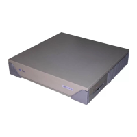
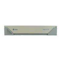
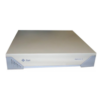
FIGURE 1-1 Front Panel of the SPARCclassic and SPARCstation LX System Units 1-2
FIGURE 1-2 Rear Panel of the System Unit 1-3
FIGURE 1-3 System Unit Internal Components 1-4
FIGURE 1-4 Typical DSIMM 1-5
FIGURE 1-5 Typical SBus Card 1-6
FIGURE 1-6 Connecting the Major System Components 1-9
FIGURE 2-1 Default Boot Mode 2-3
FIGURE 3-1 Arrangement of Type-5 Keyboard Diagnostic LEDs 3-2
FIGURE 3-2 SPARCstation System Banner 3-3
FIGURE 3-3 System Power LED on Front of System 3-8
FIGURE 3-4 Arrangement of the Type-5 Keyboard LEDs 3-9
FIGURE 4-1 Power Supply Connector 4-4
FIGURE 4-2 DSIMM Slot Locations 4-8
FIGURE 7-1 Opening the System Unit 7-3
FIGURE 7-2 Attaching the Wrist Strap 7-4
FIGURE 7-3 Closing the System Unit 7-6
FIGURE 7-4 Reconnecting System Components 7-7
FIGURE 8-1 Removing and Replacing the Power Supply 8-3
FIGURE 8-2 Removing and Replacing the Speaker/Power LED Assembly 8-6
 Loading...

