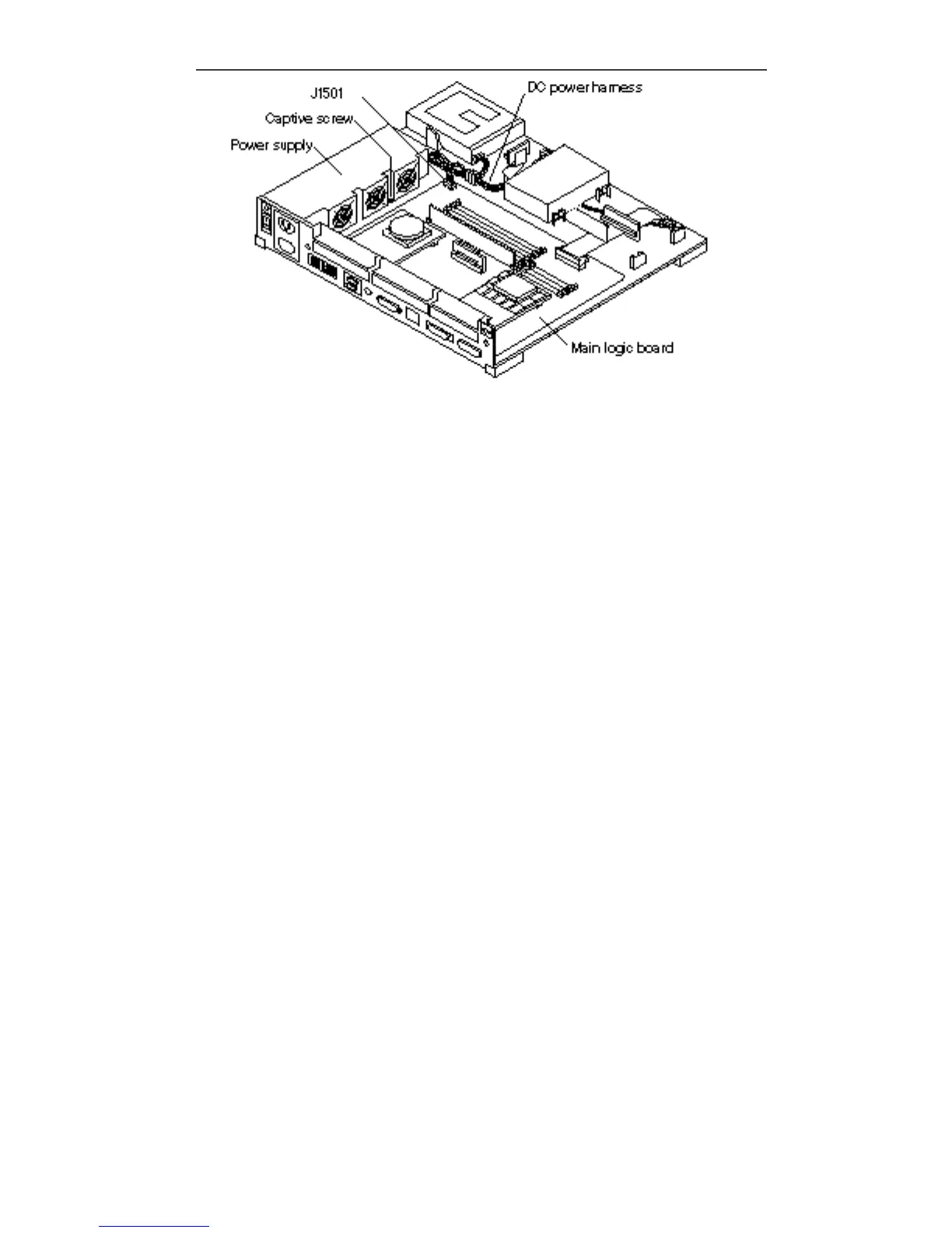
Figure 11–3 Connecting the Power Supply
4. Connect the DC power connector to the main logic board (J1501).
The connector is keyed so that the connectors can only be connected one way. See
Figure 11–3.
5. Connect the DC power connector to the DC power harness.
See Figure 11–3.
6. Make sure the power switch on the system unit is in the Off position. Press the
side labeled O.
7. Plug in the system unit power cord.
8. Follow the instructions in Chapter 17 to install the cover, connect any
expansion unit(s), and power on the system.
118
SPARCstation 10 Service Manual ♦ Revision A, July 1993