4
Figure 1–5 presents the main logic board layout.
4
Figure 1–6 and Figure 1–7 are exploded views of the SPARCstation 10 assembly.
4
Table 1–1 lists the acronyms used for certain parts, and their full expressions.
4
Table 1–2 describes video monitors.
Figure 1–2 Front View of the System
Figure 1–3 Rear View of the System
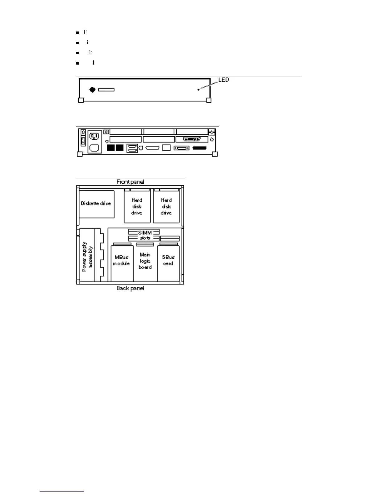
Figure 1–4 Top View of the SPARCstation 10 System without Cover
System Overview 3