1D-2 Engine Mechanical:
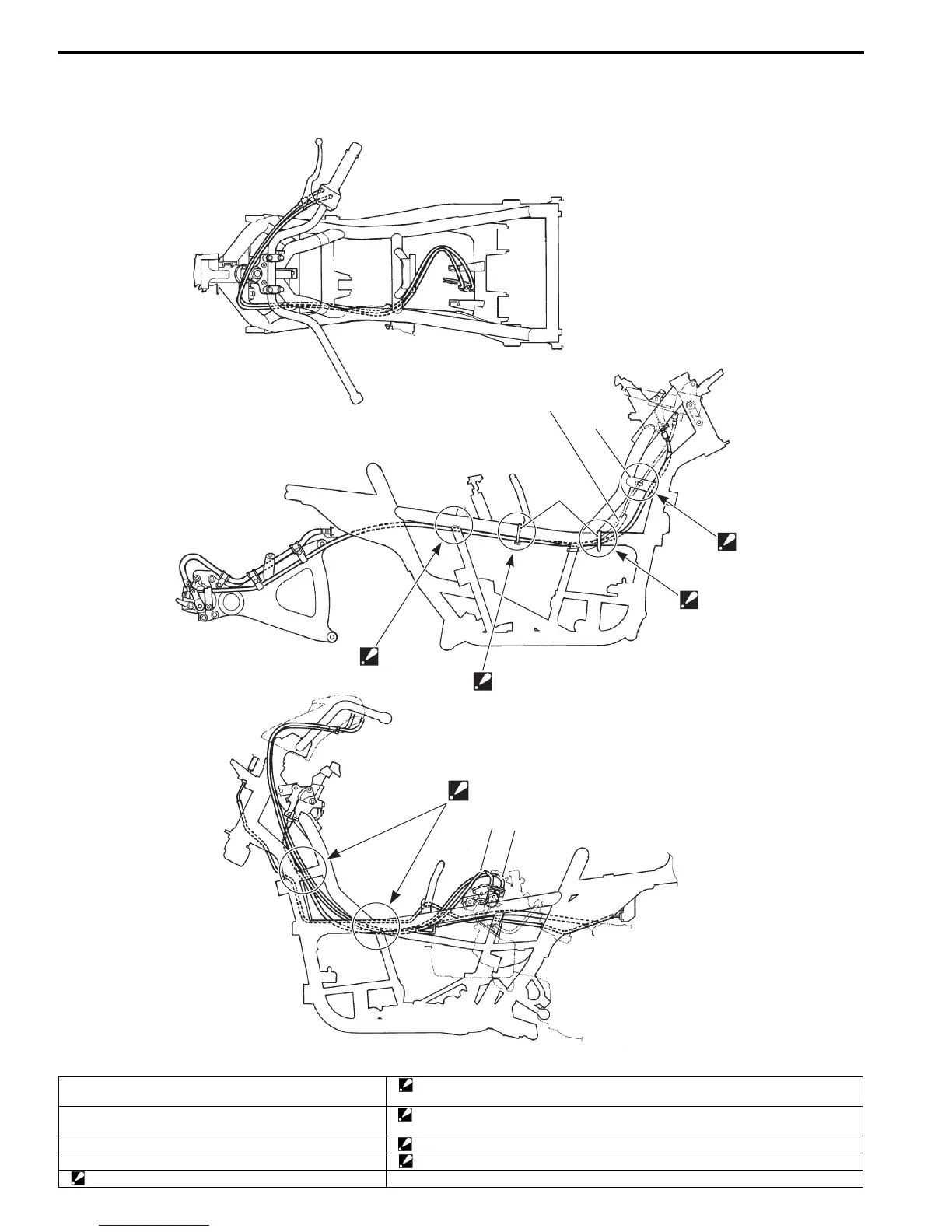
Throttle Cable Routing Diagram
B705H11402003
“E”
3
4
2
1
1
“D”
“C”
“A”
“B”
I705H1140175-02
1. Clamp “B”: Pass the throttle cables through under and inside of the frame.
Bind the brake-lock cable, starter motor lead wire and seat-lock cable together.
2. Wire harness “C”: Pass the throttle cables through inside of the frame.
Bind the parking brake cable starter motor lead wire and seat-lock cable together.
3. Throttle cable No. 1 “D”: Pass the throttle cables through inside of the frame.
4. Throttle cable No. 2 “E”: Pass the throttle cables through inside of the frames.
“A”: Pass the throttle cables through inside of the frame.

 Loading...


