EasyManuals Logo

Suzuki AN400 Service Manual

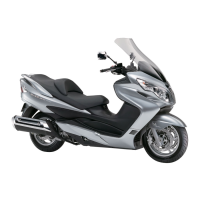
Suzuki AN400
475 pages
To Next Page IconTo Next Page
To Previous Page IconTo Previous Page
Page #214 background imageLoading...
Page #214 background image
1F-3 Engine Cooling System:
Engine Coolant Temperature Sensor Description
B705H11601004
The following circuit diagram shows the electrical wiring for the thermometer. The major components are ECT sensor
in contact with coolant, and engine coolant temperature meter.
Battery
Main fuse
Fuse
Fuse
Speedometer
ECM
R
R
R O O
O
Dg
O/B O/W
O/W B/Br B/G
O/G
O/G
B/W
B/G
ECT
Ignition
switch
I705H1160060-03
Dg: Dark green B/Br: Black with Brown tracer O/G: Orange with Green tracer
O: Orange B/G: Black with Green tracer O/W: Orange with White tracer
R: Red O/B: Orange with Black tracer P/W: Pink with White tracer

Table of Contents

Other manuals for Suzuki AN400

Questions and Answers:

Question and Answer IconNeed help?

Do you have a question about the Suzuki AN400 and is the answer not in the manual?

Suzuki AN400 Specifications

General IconGeneral
Fuel SystemFuel injection
StarterElectric
Front SuspensionTelescopic, coil spring, oil damped
Rear SuspensionSwingarm type, coil spring, oil damped
Engine Type4-stroke, liquid-cooled, single-cylinder, DOHC
Bore x Stroke81.0mm x 77.6mm
Front BrakesDisc brake
Rear BrakesDisc brake
Rear Tire150/70-13M/C 64S, tubeless

Related product manuals